• Please review our updated Terms and Rules here

Astec power supply AA11040B ticking problem when cold

retrogear

Veteran Member
Joined
Jan 29, 2014
Messages
1,126
Location
Minnesota
This one has me stumped. I have replaced all caps and still have the same symptom. When I power on with just a bare II+ or IIe (no cards) it will just tick for awhile (maybe a few seconds)then beep and boot ok. The more load I put on like adding a memory card, the longer it has to warm up before it will boot ok. When it finishes booting, the outputs measures a rock solid +5.0V, -5.0V, +12.2V, -12.2V and varying the AC120V up and down with a variac +- 5V or so all the output voltages remain solid. There is a shutdown SCR monitoring the +12V line which Sams ComputerFacts CC1 shows as 11.7V so maybe 12.2V is a little high? I'm pretty sure by using my scope that the SCR is firing causing the tick cycle. Any thoughts? My only thought at the moment is the type of caps I put in? I remember years ago in electronics class learning about the power factor of a capacitor. Would our modern day 'teeny' caps have a weak power factor?

Larry G
 
Modern caps work fine. However I have found a few faulty when brand new, so I routinely test caps now before using them.

When a supply has trouble starting up the problem is usually C7 (220uf), R2 R3 (150k), Q1 (2sd592/2sd467) or an open circuit winding on the feedback transformer.
As for the over voltage SCR, the Zener value according to my schematic should be 9.8v

Regulation is based of the +5v line, but over voltage uses the +12v. If your +5v line is working too hard the +12v goes over voltage and shuts the supply down. So you could also look for problems on the +5v rail. Recheck the capacitors you fitted are good.
Its possible that one of the rectifier diodes is breaking down with the switch on surge, but that wouldn't be my first guess. If you do replace them make sure they are fast recovery diodes and not general purpose rectifier diodes.

Also the supply work before the recap?


Edit: If you want to test what voltage triggers the over voltage protection, use a lab supply connected to the +12v and with the power supply unpowered turn up the voltage on the lab supply until its over current protection kicks in. It wont harm the power supply.

Update: So you have something to compare with, I just did that same test on a working supply and the over voltage kicked in at 13.2v

This one has me stumped. I have replaced all caps and still have the same symptom. When I power on with just a bare II+ or IIe (no cards) it will just tick for awhile (maybe a few seconds)then beep and boot ok. The more load I put on like adding a memory card, the longer it has to warm up before it will boot ok. When it finishes booting, the outputs measures a rock solid +5.0V, -5.0V, +12.2V, -12.2V and varying the AC120V up and down with a variac +- 5V or so all the output voltages remain solid. There is a shutdown SCR monitoring the +12V line which Sams ComputerFacts CC1 shows as 11.7V so maybe 12.2V is a little high? I'm pretty sure by using my scope that the SCR is firing causing the tick cycle. Any thoughts? My only thought at the moment is the type of caps I put in? I remember years ago in electronics class learning about the power factor of a capacitor. Would our modern day 'teeny' caps have a weak power factor?

Larry G
 
Last edited:
I have replaced all caps and still have the same symptom........

As if its probably a PWM switching supply the capacitors has to be of a LOW ESR-Type.
So replace again with good type of Capacitors.

If that does not help there is an other problem.
Maybe then some ZenerDiode that will check the output voltage and return that via a OptoCoupler back to the input driver.
(If it is a PWM-power supply)
Look at your PSU to find out if it is just a transformer with some regulators or lot of electronics to be a PWM.

Other issue may be a bad solder or wire connection that will drop the voltage.
So measure at start up as well at de PSU as on your board, they should be the same.
Check several points at your board, may be a bad or half blown pcb wire or connection.

Fi if the resistance of a connection is app 1 Ohms and the drawn current is 2Amperes
U=IxR
Udrop = 2Ax1Ohm is 2 Volts.

Or at your mainboard there is still a bad capacitor, then you have luck...
All the Ic's have a filter capacitor about 10nF or 100nF across the power line of each IC.
If one is bad it is very hard to find.
Only by measuring across the board to find a place were is is a bit tiny lower then elsewhere.

To figure out, PSU or main board, Manualy Load your PSU with a resistor and find out if the problem is your PSU.
Best thing is to try with an other PSU or mainboard.

To calculate the load resistor
U = IxR (I in Ampere R in Ohms)
Powerrating resistor is P=UxI
So 5V and 2 A =>
R= U/I => R = 2,5 Ohms
Powerrating Resistor is 5x2 = 10 Watts

Have fun.
 
Last edited:
To be clear the Astec AA11040B does not require low ESR capacitors.

I have 15 recapped and repaired supplies sitting here all working fine with cheap ebay capacitors. The diodes, transistors and the SCR are also not value critical for correct regulation, so long as the replacement can handle the voltage and current the regulation self adjusts. I often have to guess at replacements on clone supplies when the manufacturer has removed the part identification.

Even the feedback transformer is pretty forgiving. I've had 3 or 4 with open circuit windings and I simply wind about 30 turns of enameled copper wire over the top to replace the open winding and it works fine.

You don't even need to load the supply with a motherboard or dummy load. They start up and regulate just fine with no external load.
 
David,
Ok no LOW ESR caps, normaly a PWM-PSU needs them to keep the tempature low of the capacitors.
ESR is the resistance at a frequency, and due to the high frequency there are in pwm's LOW ESR is normaly needed.
But you've tested it, OK

The Load is now needed to see if the power supply indeed can deliver the amps, the fact that it will not start up good.
Or just measure the voltage => and more the rimple on it.

SO to check that AC component just put the meter on AC,
The now measured AC is the rimple on the DC and should be way below 100mV's AC.
 
I don't want to get into an argument but how many Astec AA11040B supplies have you repaired recently?

I know exactly what ESR is, general theory is great but I am talking about actual practical proven knowledge. I am very familiar with this specific power supply.

As for temperature, the original capacitors used in the supply are not low ESR and modern replacements being much smaller dissipate the heat much better than the originals.
The smaller size also allows the use of greater working voltage, if you are familiar with ESR then you will know that the higher the working voltage the lower the ESR.

For instance the 1000uF 16v caps used typically have an ESR of around .15 using a modern physically smaller cap with a working voltage of 25v will have and ESR of .08


David,
Ok no LOW ESR caps, normaly a PWM-PSU needs them to keep the tempature low of the capacitors.
ESR is the resistance at a frequency, and due to the high frequency there are in pwm's LOW ESR is normaly needed.
But you've tested it, OK

The Load is now needed to see if the power supply indeed can deliver the amps, the fact that it will not start up good.
Or just measure the voltage => and more the rimple on it.

SO to check that AC component just put the meter on AC,
The now measured AC is the rimple on the DC and should be way below 100mV's AC.
 
I worked on switch mode power supplies of various forms many years so yes, I know when it puts more current out for the 5V line which is the reference for sample, the other secondaries rise.
Ok here's what I found. There are 4 1000uf 16V caps on the 5V output with one stacked to the 12V line which I had replaced along with all the other caps with Nichicon brand. I decided to swap
out those 4 again with Panasonic ones I had. As I replaced each cap, the amount of load it could handle increased w/o ticking shutdown. After all 4 replaced, I had a little buzzing noise which remained under
full load, and at cold startup it would still tick once or twice then boot. So I added an additional 1000uf in parallel with the last in 5V line. No buzzing and is rock solid with many cards cold or not.
These damn caps are not what they used to be !!!

Larry G
 
It sounds like the change is just masking the real fault. The capacitors are not nearly that critical.

Given the change in symptoms the extra capacitor made I'd be looking at issues on the base drive of the main switching transistor and the feedback circuit. It seems the kickstart voltage is not kicking off the oscillations properly.
Of the last 15 of those power supplies I've repaired, 3 of them had the same winding on the feedback transformer open circuit. With that winding OC the primary side would charge, the kickstart surge would hit the secondary side but oscillation would not start. It's possible your feedback transformer winding is intermittent OC, my recent experience of 20% of the recent faults being that transformer would place it high on the suspect list.

I worked on switch mode power supplies of various forms many years so yes, I know when it puts more current out for the 5V line which is the reference for sample, the other secondaries rise.
Ok here's what I found. There are 4 1000uf 16V caps on the 5V output with one stacked to the 12V line which I had replaced along with all the other caps with Nichicon brand. I decided to swap
out those 4 again with Panasonic ones I had. As I replaced each cap, the amount of load it could handle increased w/o ticking shutdown. After all 4 replaced, I had a little buzzing noise which remained under
full load, and at cold startup it would still tick once or twice then boot. So I added an additional 1000uf in parallel with the last in 5V line. No buzzing and is rock solid with many cards cold or not.
These damn caps are not what they used to be !!!

Larry G
 
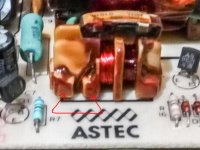
I've marked the most common failing components on this supply.
IMG_20170227_173210.jpg

This is a closeup and how I've been repairing the OC winding. On all three it was this same winding that failed. This particular supply initially worked after the recap on the primary side. It died a short time later and would not start up, after checking every other components on the primary side and testing the feedback circuit by externally powering the +5v line from my lab supply, the only thing left to blame was the feedback transformer. So I pulled it and checked the winding resistances to find one winding OC. I figured I had nothing to lose by trying to add a new winding. It worked so I checked the other two supplies I had that wouldn't start up and found the same problem.
IMG_20170227_173249.jpg
 
I'm sure you're correct. Those windings check good resistance according to Sam's. Are you saying the continuity opened when you removed the transformer?
In my past troubleshooting, I did notice the performance improved when I soldered the board, including that transformer. Someone else is having this problem too
and got it working by soldering the board. I wonder if the problem is a resistive connection where the enamel wire is attached to the pin? I noticed the 20V feedback waveform
I circled changes on-time as it first warms up. The odd thing is it's every other pulse !!! I suppose each base winding on the secondary represents on-time and off-time.
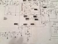
I wonder when you desolder the transformer if it opens that contact point? I have my own Sams CC1 paper schematic and I circled C7 many years ago as a problem child.
IMG_0113.jpg
 
It could well be a dry joint or a fractured track, that would explain getting warm up helping it startup.
Definitely worth the effort to resolder the joints and maybe flow a little fresh solder along the tracks.

The feedback transformer in mine just decided to die even before I pulled it out.

I'm sure you're correct. Those windings check good resistance according to Sam's. Are you saying the continuity opened when you removed the transformer?
In my past troubleshooting, I did notice the performance improved when I soldered the board, including that transformer. Someone else is having this problem too
and got it working by soldering the board. I wonder if the problem is a resistive connection where the enamel wire is attached to the pin? I noticed the 20V feedback waveform
I circled changes on-time as it first warms up. The odd thing is it's every other pulse !!! I suppose each base winding on the secondary represents on-time and off-time.
I wonder when you desolder the transformer if it opens that contact point? I have my own Sams CC1 paper schematic and I circled C7 many years ago as a problem child.
View attachment 36613
 
I tested my re-capped (over-capped) supply for several hours with a heavy load of an A2+ with a couple RamFactor cards, serial card, disk controller. It got plenty warm but not hot and ran just fine so I'm calling it fixed.
I have another Astec supply same model but silver case instead of copper colored with same symptom: ok except when loaded with a few cards then shuts down into tick mode. I opened it to start recapping and the four
mains caps are puffy but 100uF 250V instead of 47uF !!! Now I need to order those. Why the change? Did Astec realize there was a power issue?
 
The only Astec supplies I've seen here all use 4x47uF. The was a supply made by a US manufacturer toward the end of the 2e production that uses 2x100uF. The DC power connector exits from the side of the supply rather than the end like the Astec supplies.

The common problems with that supply was the resistors across the mains caps, I think they are 150k and a small electrolytic capacitor in the PWM feedback circuit. I think its value is about 10uf or something, but its been a while since i worked on one.

If there are 4 caps, maybe it has been recapped by somebody in the past with the larger caps. With 4 caps you will be fine replacing them with 47uF

I tested my re-capped (over-capped) supply for several hours with a heavy load of an A2+ with a couple RamFactor cards, serial card, disk controller. It got plenty warm but not hot and ran just fine so I'm calling it fixed.
I have another Astec supply same model but silver case instead of copper colored with same symptom: ok except when loaded with a few cards then shuts down into tick mode. I opened it to start recapping and the four
mains caps are puffy but 100uF 250V instead of 47uF !!! Now I need to order those. Why the change? Did Astec realize there was a power issue?
 
So this power supply I replaced the mains caps with 4 100uf 250v. Replaced all the other caps. Worked good except "hissing" noise under heavy load like the previous supply.
This time I special ordered 1000uf 16V caps specified as low ESR, put one in C19 replacing the new cap that was already installed. Hissing noise is gone and rock solid with heavy load !!
Evidently low ESR does matter.

Larry G
 
I'm not convinced, I think it was a confidence. I normally don't use low esr caps and have no issues. The one supply I have that does hiss a little is a clone supply that I did use low ESR caps in. I find the noises are generally from vibrations, if it bothers you a little bit of flexible hot melt glue or silicone will solve it.


Edit: I took some ESR readings. Good original (1000uF 16v) caps pulled from astec supplies typically read .04 ohms. Low ESR caps of the same value read around 0.2 ohms. Unlike capacitors from the 80's modern caps have very little headroom on voltage, where a 16v cap from the 80's would generally be happy at 20v the same isnt true of modern caps which are spec'ed very close to the maximum. Interestingly the ESR of a 1000uF 25v capacitor reads the same as the old 16v caps, 0.4 ohms. My guess is those old 16v caps would these days be labeled 25v. So if you really want to match the components close to the original spec, use 25v caps to replace 16v caps.


So this power supply I replaced the mains caps with 4 100uf 250v. Replaced all the other caps. Worked good except "hissing" noise under heavy load like the previous supply.
This time I special ordered 1000uf 16V caps specified as low ESR, put one in C19 replacing the new cap that was already installed. Hissing noise is gone and rock solid with heavy load !!
Evidently low ESR does matter.

Larry G
 
Last edited:
Back
Top