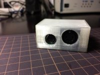
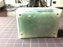
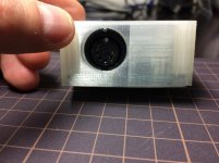
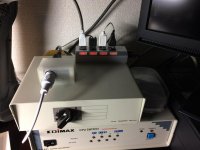
The AT2XT keyboard converter (AT2XTKB) project is a Vintage Computer forum driven project to develop and manufacturer a keyboard adapter which allows users to attach AT keyboards to XT class computers. This, for example, allows XT machines to be used on KVM (keyboard/Video/Mouse) switches.
The project is entirely open source, from the design, schematic, layout, bill of materials, and firmware.
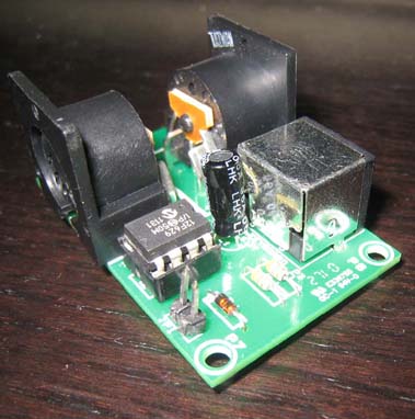
This page will provide links to all the resources utilized in the project.
You can discuss this project here
[h="2"] The PIC Chip [/h]
The heart of the circuitry is a PIC12F629 integrated circuit, referred to as "PIC chip" in other sections of this page.
From the factory, the EEPROM component within the PIC12F629 contains no firmware and therefore needs to be programmed. An EPROM programmer is required to write firmware into the PIC12F629. The custom firmware created for the PIC12F629 in the AT2XTKB is available via a link below, in the 'Downloads' section.
[h="2"] Scancode E0 Pass-Through [/h]
In August 2010, it was identified that certain non-US scenarios need to have the E0 scancode passed straight through the AT2XTKB. The VCF discussion on this starts [here].
After investigation on how to implement that, it was discovered that the AT2XTKB would need to be able to work in one of two modes:
1. Do not pass-through scancode E0; or
2. Pass-through scancode E0.
It was decided to modify the PIC chip's firmware (became version 0.93) and use the then unused jumper, JP1, to select the mode of operation. At that time, the design flaw in regard to jumper JP1 was detected (see 'Jumper JP1' section below).
If you are in the rare situation of needing 'scancode 0xE0 pass-through' functionality on your AT2XTKB, you will need to:
1. Per the 'Jumper JP1' section below, modify your AT2XTKB to cater for the JP1 flaw; then
2. Per the 'Jumper JP1' section below, set jumper JP1 as required.
[h="2"] Jumper JP1 [/h]
At the design time of the AT2XTKB, jumper JP1 was not used, included for possible future use.
Later, when the PIC code was being changed to cater for 'scancode E0 pass-through' functionality, it was discovered that there was a design flaw in the AT2XTKB that prevented proper jumper use.
The flaw does not affect the vast majority of AT2XTKB users - the AT2XTKB works as expected - there is no need to address the flaw.
For those who need 'scancode E0 pass-through' functionality, the flaw needs to be fixed by adding a pullup resistor, R3, of a value of 47K ohms (actually, anything between 2K and 100K ohms) between pin 1 (Vcc) and pin 4 of the PIC chip.
Jumper settings:
Pullup R3 not present and JP1 on: Normal operation
Pullup R3 not present and JP1 off: Normal operation
Pullup R3 present and JP1 on: Normal operation
Pullup R3 present and JP1 off: Scancode E0 passed through
[h="2"] Downloads [/h]
[h="3"]Firmware for PIC Chip (PIC12F629)[/h]
Firmware - version 0.94 - Source code
Firmware - version 0.94 - HEX file (What your EPROM programmer uses.)(Click here for info about the OSCCAL value.)
[h="3"]PCB/Schematic[/h]
Schematic view #1
Schematic view #2 (Resistor R3 not shown.) (Due to a limitation in the drawing software, the arrangement of pins on large DIN connectors is wrong.)
Schematic view #3 (Resistor R3 not shown.)
Schematic as an Eagle file
PCB board layout (Seems slightly out of date-there are now mounting holes in the corners.)(Holes for large DIN connectors facing wrong way.)
View attachment XTATKEY_094.zip
[h="2"] Bill of Materials [/h]
Parts sourced from Digikey Electronics
[wiki]Category:Hardware[/wiki]
The project is entirely open source, from the design, schematic, layout, bill of materials, and firmware.

This page will provide links to all the resources utilized in the project.
You can discuss this project here
[h="2"] The PIC Chip [/h]
The heart of the circuitry is a PIC12F629 integrated circuit, referred to as "PIC chip" in other sections of this page.
From the factory, the EEPROM component within the PIC12F629 contains no firmware and therefore needs to be programmed. An EPROM programmer is required to write firmware into the PIC12F629. The custom firmware created for the PIC12F629 in the AT2XTKB is available via a link below, in the 'Downloads' section.
[h="2"] Scancode E0 Pass-Through [/h]
In August 2010, it was identified that certain non-US scenarios need to have the E0 scancode passed straight through the AT2XTKB. The VCF discussion on this starts [here].
After investigation on how to implement that, it was discovered that the AT2XTKB would need to be able to work in one of two modes:
1. Do not pass-through scancode E0; or
2. Pass-through scancode E0.
It was decided to modify the PIC chip's firmware (became version 0.93) and use the then unused jumper, JP1, to select the mode of operation. At that time, the design flaw in regard to jumper JP1 was detected (see 'Jumper JP1' section below).
If you are in the rare situation of needing 'scancode 0xE0 pass-through' functionality on your AT2XTKB, you will need to:
1. Per the 'Jumper JP1' section below, modify your AT2XTKB to cater for the JP1 flaw; then
2. Per the 'Jumper JP1' section below, set jumper JP1 as required.
[h="2"] Jumper JP1 [/h]
At the design time of the AT2XTKB, jumper JP1 was not used, included for possible future use.
Later, when the PIC code was being changed to cater for 'scancode E0 pass-through' functionality, it was discovered that there was a design flaw in the AT2XTKB that prevented proper jumper use.
The flaw does not affect the vast majority of AT2XTKB users - the AT2XTKB works as expected - there is no need to address the flaw.
For those who need 'scancode E0 pass-through' functionality, the flaw needs to be fixed by adding a pullup resistor, R3, of a value of 47K ohms (actually, anything between 2K and 100K ohms) between pin 1 (Vcc) and pin 4 of the PIC chip.
Jumper settings:
Pullup R3 not present and JP1 on: Normal operation
Pullup R3 not present and JP1 off: Normal operation
Pullup R3 present and JP1 on: Normal operation
Pullup R3 present and JP1 off: Scancode E0 passed through
[h="2"] Downloads [/h]
[h="3"]Firmware for PIC Chip (PIC12F629)[/h]
Firmware - version 0.94 - Source code
Firmware - version 0.94 - HEX file (What your EPROM programmer uses.)(Click here for info about the OSCCAL value.)
[h="3"]PCB/Schematic[/h]
Schematic view #1
Schematic view #2 (Resistor R3 not shown.) (Due to a limitation in the drawing software, the arrangement of pins on large DIN connectors is wrong.)
Schematic view #3 (Resistor R3 not shown.)
Schematic as an Eagle file
PCB board layout (Seems slightly out of date-there are now mounting holes in the corners.)(Holes for large DIN connectors facing wrong way.)
View attachment XTATKEY_094.zip
[h="2"] Bill of Materials [/h]
Parts sourced from Digikey Electronics
Code:
Qty  Digikey #              Item
1                        AT2XT Keyboard PCB (get this from andrew lynch) or breadboard your own
2    CP-2350-ND          CONN DIN 5 PIN FEMALE PCB
1    CP-2260-ND             CONN MINI-DIN 6 PIN FEMALE PCB (yes, 6 pin.  do not get 5 pin PS/2 connectors!)
1    PIC12F629-I/P-ND    IC MCU CMOS FLASH-BASE 8BIT 8DIP
1    A24807-ND           CONN IC SOCKET 8POS DIP TIN
1    568-1360-1-ND       DIODE SW HS 100V 200MA DO-35
2    P4.7KBACT-ND        RES 4.7K OHM CARBON FILM 1/4W 5%
1    P10375TB-ND         CAP 47UF 25V ELECT M RADIAL
1    A30916-ND           CONN HEADER VERT 2POS .100 TIN (there's a million of these types of headers - not actually req'd)
1    ?                   47K ohm resistor (R3) between pin 4 and Vcc. (only needed for jumper to select different operation for non-USA keyboards)
Last edited by a moderator:

