• Please review our updated Terms and Rules here

Attaching a battery to a 386 motherboard

Why do you suppose that IBM designed a double-diode there instead of what I assume to be an equally effective and less costly single-diode?
A new 6V nominal lithium battery will measure significantly more that 6V. I think that the intention of two-versus-one-battery-diode was to drop more voltage, as Chuck(G) suggested. It would mean that the resulting voltage that reaches the 'x to 6V' RTC chip is comfortably under 6V, and another consideration is the '+5V switch' circuit.

Was it IBM? Could have been; the MC146818 datasheets that I see show a simpler arrangement:
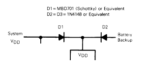
1709411455474.png
Note that in that arrangement, D2 is specified as 1N4148 (or equivalent), and not a Schottky type like D1. The designer must want a greater voltage drop from the '6v nominal' battery.

( The datasheet of the OPTi 82C206 shows that for the 82C206, OPTi recommends the 'two 1N4148 battery diodes, and a +5V switch' arrangement. Relevant area of the datasheet shown at [here]. )
 
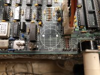
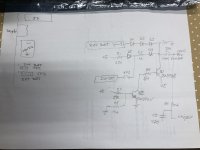
Before connecting anything to mine (after Varta juice repairs), I traced out a partial schematic of that area, to see if I'd be safe with the external battery pack.
IMG_1436_2023-12-19.jpg
 
Before connecting anything to mine (after Varta juice repairs), I traced out a partial schematic of that area, to see if I'd be safe with the external battery pack.
Three diodes for the 'external' battery !
Good that you are going with a 4.5V battery holder. (With new batteries, measuring, say 4.6V to 4.8V)
3V, surely, will not 'cut the mustard'.

{R1 + D5} charge the 'internal' battery.

{Q1 + Q2 + associated components} are the +5V switch.

The capacitor allows for a battery change (within a reasonable period of time) without losing CMOS/RTC content.
 
I wonder if a small LiFePO₄ cell connected to the internal battery terminals would do the job. Heaven knows, the charging current isn't very high and the LiFP batteries are pretty tolerant (not like the Li ion ones). Just musing a bit--a standard lithium AA size primary cell should endure for years in any case.
 
A new 6V nominal lithium battery will measure significantly more that 6V. I think that the intention of two-versus-one-battery-diode was to drop more voltage, as Chuck(G) suggested. It would mean that the resulting voltage that reaches the 'x to 6V' RTC chip is comfortably under 6V, and another consideration is the '+5V switch' circuit.

Was it IBM? Could have been; the MC146818 datasheets that I see show a simpler arrangement:
View attachment 1274752
Note that in that arrangement, D2 is specified as 1N4148 (or equivalent), and not a Schottky type like D1. The designer must want a greater voltage drop from the '6v nominal' battery.

( The datasheet of the OPTi 82C206 shows that for the 82C206, OPTi recommends the 'two 1N4148 battery diodes, and a +5V switch' arrangement. Relevant area of the datasheet shown at [here]. )
I'm playing with a 286 motherboard also, which has a footprint on the motherboard for (what looks like a) coin cell holder or barrel battery, and has one diode drop between the battery and the MC146818 Vdd pin. Measures 2.5V with a fresh 2032 battery temporarily connected.

(( EDIT: OK, I claimed one diode drop above, but tracing the ckt a bit I see there's two diodes in series to the CMOS chip. And the fresh battery I pulled out measures 3.3V unloaded (not 3V as advertised). ))

A charged Varta would be 3.6V?

I see nothing in the datasheet indicating the chip works below 3V.

There's also a connector for an external battery pack, and a jumper to charge the battery.

IMG_1467.jpg
 
Last edited:
I'm playing with a 286 motherboard also, which has a footprint on the motherboard for (what looks like a) coin cell holder or barrel battery, and has one diode drop between the battery and the MC14681 Vdd pin. Measures 2.5V with a fresh 2032 battery temporarily connected.
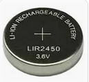
Suggesting that for the soldered-in-coin-battery option, a li-ion coin battery may have been intended.

1709500517229.png

A charged Varta would be 3.6V?
Some brand new 3.6V barrel shaped Ni-CD batteries that I bough a few years back, measured 3.7V
 
Suggesting that for the soldered-in-coin-battery option, a li-ion coin battery may have been intended.
From the chips, it looks like a 1988 dated motherboard. From what I'm reading, Li-ion batteries were not introduced until three years later.

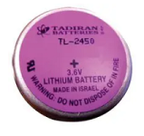
So perhaps Lithium. (Not rechargeable.)

1709501315942.png
 
I haven't really traced out the circuit on the 286 very carefully (it's currently stuffed with boards, etc), but I just noticed not too far away is a pair of 2N3904/2N3906 and similar circuit to what's in the 386 I posted earlier.

And this one has two diode drops between the battery socket footprint and the 146818 chip. (I incorrectly claimed one drop before)
The fresh coin cell I pulled out measure 3.3V with no load.
 
Last edited:
Back
Top