• Please review our updated Terms and Rules here

Bootstapping Cromemco 4FDC

I have a 64K board but it is dynamic so it doesn't play well with the front panel. I have 32K plus another 8K board of static. I would have to modify the ZPU board to refresh dynamic.
There are 4 options with keeping in mind that in the end I would like to be able to use my front panel to do the simple things an IMSAI is known to do.
1) Buy enough static ram to fill 64K.
2) Wire the ZPU to support refresh for the Measurement Systems and Control Inc. Model DMB 6400 and figure something later for the front panel later.
3) Setup bank selecting/phantom select stuff. (sounds complicated)
4) I bought a JAIR Single Board Computer that is not assembled but could be used as a last resort.

Thanks for the help
My understanding is the DMB6400 board was designed to support Cromemco's bank switching, so if you were willing to forget about having it work with the front panel you could likely get a 64K Cromemco CDOS system running on it.

No question the easiest most reliable way to get a working system is to use the JAIR board. With a JAIR board in your IMSAI box (a) you do not need any other boards in the system, (b) the front panel is fully functional, and (c) you can run CP/M directly from the ROM monitor and SD card software provided for the board. You don't need to mess with any vintage equipment, drive controllers, or disk drives to get a JAIR board up and running with CP/M.
 
No question the easiest most reliable way to get a working system is to use the JAIR board. With a JAIR board in your IMSAI box (a) you do not need any other boards in the system, (b) the front panel is fully functional, and (c) you can run CP/M directly from the ROM monitor and SD card software provided for the board. You don't need to mess with any vintage equipment, drive controllers, or disk drives to get a JAIR board up and running with CP/M.
Kinda feels like cheating
 
I found an interesting article about CDOS and Cromemco 4FDC. They talk about different versions of CDOS and what hardware it expects.
Looking at what Cromemco cards I have it looks like my machine will be similar to a Cromemco System 3.
It also looks like most CDOS or CP/M is built for 64K. I noticed in the article you can put 8K just below the RDOS EPROM and 32K and the start of memory but I do not have static boards in that combination where I can move them around in memory.
The article also talk about CDOS initializing a TUART board. I was assuming that CDOS would keep spitting out console messages on the 4FDC serial port. Do I need to install the TUART board? I will stick it in and try it but I doubt that is the problem.
I will work on making sure the ZPU will auto jump to the RDOS ROM and I have to modify the 64K DRAM board to phantom signal over the memory region that the ROM sits at.

I think your system will be more like a Cromemco Z2, with a bit of crossover to a Z1 because of your IMSAI front panel. The Z2 had a ZPU, a 4FDC, one or more 16KZ RAM boards, 5.25" floppy drives, and a TU-ART board. The TU-ART board is optional - you don't need to install one since the console can stay on the 4FDC serial port.
The Cromemco System 3 was a significant step up from the Z2 with at least 64K or more of RAM, and a 16FDC controller with at least a couple of built-in 8" drives.
 
Last edited:
I have a 64K board but it is dynamic so it doesn't play well with the front panel. I have 32K plus another 8K board of static. I would have to modify the ZPU board to refresh dynamic.

You are conflating some things here. Dynamic RAM is not incompatible with front panel usage. Specific board designs can be compatible or not. Later DRAM boards tended to drop the additional circuitry needed for front panel use since ROM based bootstraps became affordable.

There is no modification required for the Cromemco ZPU to support dynamic RAM. Z80 refresh cycles are not extended over the S100 bus since it is really an 8080 bus. So most DRAM cards generate their own transparent refresh.

If you want all those things at the same time, DRAM, front panel use, and Cromemco compatibility you will need to buy cards with those specific characteristics. Most likely best place to start would be two Cromemco 16KZ cards since they can switch in and out with RDOS in the upper 32K and your static card could exist in the lower 32K. Technically only the card at C000h would need the bank enable support.

There are 4 options with keeping in mind that in the end I would like to be able to use my front panel to do the simple things an IMSAI is known to do.
1) Buy enough static ram to fill 64K.

This would work if the upper 32K card(s) support Cromemco bank select or PHANTOM + 4FDC mod to support PHANTOM.

2) Wire the ZPU to support refresh for the Measurement Systems and Control Inc. Model DMB 6400 and figure something later for the front panel later.

The ZPU needs no modification for this combination. That memory card has onboard transparent refresh. It may not work with the front panel since by the time 64KB DRAM cards came out manufacturers were dropping that capability.

3) Setup bank selecting/phantom select stuff. (sounds complicated)

Bank select is easy if you get the correct cards. PHANTOM would require mods which could be complicated.

4) I bought a JAIR Single Board Computer that is not assembled but could be used as a last resort.

JAIR is an 8080 board and won't work with 4FDC or CDOS which require a Z80.

Boils down to this:

1. ZPU is fine.
2. 32K SRAM starting at 0000h is fine. It will work with your front panel.
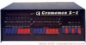
3. Install two Cromemco 16KZ cards at 8000h and C000h. Jumper card at C000h to be disabled at reset. RDOS will enable it at boot. I haven't checked the 16KZ manual but I suspect they would work with the IMSAI front panel since Cromemco themselves sold an IMSAI chassis with a ZPU and 16KZ cards in it branded as the Cromemco Z-1.

1702239064376.jpeg
 
I just looked at the manual for the DMB-6400 after @hmb mentioned it supports Cromemco bank switching. So you should be able to configure it to disable half the card and do the Cromemco bank enable for the upper 32K. This would work in the place of two 16KZ cards.

Used with your static RAM at 0000h you'd be able to use the front panel for the lower half and still boot CDOS with the 4FDC.
 
I am going to try configuring the Dram board for bank selecting but I am confused. on page 15 of the DMB 6400 manual is talks about header 2 and wiring banks to IO pins and the choice of data pin to use is in software. I have no idea what they mean or I am not understanding how this works.
Maybe I am confused about using I/O ports to enable and disable banked memory.
If someone can elaborate and maybe give me an idea of how to wire header 2 so I only have (2) 16K banks in the upper half of the system with bank selection for memory at C000h and the other 32K is disabled.
 
Cromemco selects memory banks by writing a value to port 40h. Each bit position represents a bank so any memory boards assigned to that bank will be enabled when that bit is set. You would want to make the two lower 16K chunks on that board disabled and/or assigned to no bank. You would want to make the two upper 16K chunks belong to say bank 1 (bit position 1). It might even need to be set to all the banks but I need to understand how CDOS does it better. I know Cromix much better than CDOS memory settings. One 16K chunk should have its base address as 8000h and the other should have its base address as C000h. If there is a way to have them disabled at reset you need to configure it that way.
 
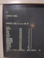
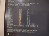
I got the machine to boot. After adding another 16K of ram so 48K total made it work. I am going to do some more testing. and also attempt to boot with 8" disk images.
I will post some information soon. So exciting. Thank you to everyone that has helped.
IMG_20231211_194338270.jpg
 
I got the machine to boot. After adding another 16K of ram so 48K total made it work. I am going to do some more testing. and also attempt to boot with 8" disk images.
I will post some information soon. So exciting. Thank you to everyone that has helped.
View attachment 1269573
That's great news. The directory listing in your copy of CDOS 00.20 looks different than the one I'm running in z80pack. I'm deducing that the IMD copy must be linked for 48K, while the raw block image for z80pack must be linked for 64K.

That really validates that a lot of the hardware is functional and that's a very good thing. Best of luck on the path forward.
 
The first 8" floppy I wrote started as 128 byte sectors and then turned into double density. I don't think that image will work for me. I am going to dig through DeRamp's list of images but if someone could point me to a 8" single sided / single density .IMD files that would be great.
 
The first 8" floppy I wrote started as 128 byte sectors and then turned into double density. I don't think that image will work for me. I am going to dig through DeRamp's list of images but if someone could point me to a 8" single sided / single density .IMD files that would be great.
Do you have a plan in mind for how you are going to connect a Shugart 8" drive to the 4FDC 8" drive interface, which has been designed for use with a Persci 8" drive interface?
 
I do not have a plan. I was kind of hoping that all the mods that have been done to this board it would work. wishful thinking I guess.
From glitchworks:

Floppy Drives and Data Separators​

One of the most popular arguments against the 4FDC is incompatibility with standard floppy drives. There’s some truth in this: the 4FDC was indeed designed for operation with 8” Persci 277 voice coil drives. Persci drives are expensive and unreliable, so they’re less than optimal for a practical, usable system. The 4FDC manual specifies Wangco Model 82 5.25” drives as an option as well. This particular model is somewhat uncommon, and certainly more expensive than a Shugart-compatible 5.25” drive. It’s commonly believed that these particular drives are required because the 4FDC requires a drive with an external data separator since the WD1771 doesn’t include a data separator…well, not quite!

The Western Digital WD1771 disk controller does in fact include a FM (single-density) data separator on-chip. Being an early integrated circuit design, the data separator is not particularly high-performance. This is referenced in the WD1771 datasheet, page 17:

NOTE: Internal data separation may work for some applications. However, for applications requiring high data recover reliability, WDC recommends external data separation be used.
As a result, Cromemco decided to use the data separator present on Persci 277 drives. This turns out to be less of an issue than expected, as many early 8” floppy drives (the Shugart SA-800, for example) include a FM data separator. But that still leaves the requirement for 5.25” drives that include a data separator…right?

This one is flat out incorrect – while the WD1771’s on-board data separator is indeed disabled for 8” disk access, the MINI/MAXI select line enables it for 5.25” disks. Any standard 40-track 5.25” floppy drive will indeed work perfectly with the 4FDC, provided the drive is strapped appropriately. I’m currently using a pair of Tandon TM-100 drives with my 4FDC, which successfully formats, reads, writes and boots floppy disks. Perhaps the lower data rate of the 5.25” drives makes the on-board WD1771 data separator acceptable; in any case, it seems to work.
 
This has been an interesting adventure. I have learned a lot and have thanks to everyone's help, the machine can boot CDOS. Although now I feel it is time to address the short comings of this setup and where I should go in the future.
First off the 8" drives. I seem to be able to initialize the disk just fine but I get seek errors when trying to acccess them. Also for some reason drives C and D (drive selects 2 and 3) for the floppies do not seem to respond.
I can write 8" floppies with IMD ( I did a 32kbasic.imd from Deramp) but I can't read them on CP/M.
Nformat says the drive isn't ready. I have more work to do to get the 8" drives working.
I have no problem using 5" disks if I have to. The single density software is very slim.

Almost everything I have seen uses double density. which means I am going to be very limited in getting software for this machine.
The long term question is: am I going to have to ditch the 4FDC and plan on something that can support double density.
Should I pursue 8" double density drives or just stick to 5"? I think it would be cool to have 8" drives I can use.
I still have the TEI floppy controller but I think it is over my head in getting it working.
Is there another floppy controller listed on ebay that would work for me with the cromemco hardware?

I basically comes down to software. If almost all the software is on double density, this 4fdc and single density drives will be a handicap to the system.

Any advice on which direction I should head with this problem would be appreciated.
 
Are you performing these most recent tests of your 8" drives using the 4FDC, or with these drives connected to a PC via a 34-to-50 pin adapter? If the latter, drive selects 2 and 3 on your 8" drives won't work unless your adapter allow you to manually reroute the only two drive selects provided by the standard PC floppy controller (0 and 1, or A and B) to drive selects 2 and 3 on your 8" drives.

In general terms for most hobbyists, for S100 systems your choice of floppy controller board is going to dictate the set of manufacturer boards you are going to use for critical functions that are software-dependent like the monitor and boot ROM, and console I/O. The CP/M BIOS needs to be custom-written to work with each S100 manufacturer's floppy controller board, the boot ROM they use, and the console port. There are no CP/M versions I am aware of that work interchangeably between two different manufacturer's S100 floppy controller boards. Therefore CDOS or CP/M designed for a Cromemco system will only work with their their own floppy controller, their own RDOS ROM boot, and their own console port that uses a specific type of UART at a specific I/O address located on their floppy controller boards. The only way to get around this if you have a good knowledge of 8080/Z80 language programming and how to customize a CP/M BIOS or CDOS.

Back in the day the primary selling point for DSDD 8" drives was their relatively large data capacity compared to DSDD 5.25" drives. That was really important if for example you were using your system to run a business and were running a few apps that required a lot of disk space. Today for a hobbyist running these systems, having the data capacity of an 8" DSDD drive is of lesser importance and you can get plenty of satisfaction "playing" with a system that just uses a 5.25" drive. I think the the reason to run an 8" drive now is for your own learning and sense of accomplishment, and the novelty of being able to run such a vintage piece of equipment.

I mentioned this before, but my suggestion is that you stick with 5" drives on your newly resurrected 4FDC-based Cromemco system until you manage to find a 16FDC controller. If you want to explore obtaining a DSDD S100 floppy controller capable of using standard Shugart-interface 5.25" and 8" drives from another manufacturer, make sure that you are also going to be able to obtain (a) a copy of CP/M provided by the manufacturer of that board and (b) whatever additional boards the manufacturer specifies for a minimal system - particularly the board required for connection to the system console.
 
Last edited:
Thanks for the reply hmb.
I have been trying to initalize with the s100 computer. hooking the 5" up as DS0. the 2 8" drives were DS1 and DS2. I am not doing any more that 2 floppy drives on the PC. mostly its just 1 at a time since I have been jumping the drives around trying different combination to figure out what isn't working right.
Quick update, I am noticing on the 4FDC that the only drive I can successfully access is A (drive select 0). Drive select 1 will init a disk but give seek errors. drive select 2 and 3 just hangs with no drive light. why would this be? I will do some probing and see if a signal is missing. This behavior seems to be the same for 8" and 5". I can't read from B: if hooked to either.
I am learning I can warm boot and change disks through drive A: I was able to initialize and I used IMD to write 16kbasic to 5" disk and run it. I also noticed the 16K basic disk is bootable!
I will stick to 5" for right now and keep my eye open for a 16FDC.
I think if I can figure out the drive select problem I can initialize 8" disks and read from them properly.
16kbasic.png
 
Last edited:
Another update. I can read 5" B: drive and write to it. it was because of a termination block on B:
I can't access drive select 2 and 3. I can have a 5" and an 8". C and D show no drive select signal
8" as B: I can INIT the disk but I get seek errors hex 36 when trying to read it.
I am wondering if you are not supposed to hook 8 and 5 at the same time? if the bus is being shared and with 2 sets of terminators from different cables?
 
Last edited:
Both 5" and 8" can be hooked up at the same time, but on a 4FDC the 8" have to be Persci. There are electrical signal differences as has been pointed out numerous times, and it isn't just the data separator issue. In fact there is an EJECT line coming out of the 4FDC that conflicts with an output on the Shugart drive interface. Board mods are required before Shugart drives can be connected.

The 8" bus and the 5" bus are isolated for termination. Each has to have its own terminated drive as the last drive on the chain.
 
There is one other compatibility issue as to why you might be getting seek errors. The Persci drive seek time is extremely fast and they use buffered seeks when the step count is more than one cylinder. Drives are built in pairs sharing the same head carriage so there is some software trickery to keep A/B or C/D in sync. This could mess up trying to use normal separate drives with the same driver software.

Shugart drives require a slow step pulse for every cylinder no matter how many. CDOS would have to be reconfigured for that on top of the electrical changes to the interface.

Even if you get a 16FDC, it is also designed for Persci drives. But there are documented board modifications for the electrical interface. The slow step rate required by SA80x will still be there and requires the OS driver software to be modified.
 
Another update. I can read 5" B: drive and write to it. it was because of a termination block on B:
I can't access drive select 2 and 3. I can have a 5" and an 8". C and D show no drive select signal
8" as B: I can INIT the disk but I get seek errors hex 36 when trying to read it.
I am wondering if you are not supposed to hook 8 and 5 at the same time? if the bus is being shared and with 2 sets of terminators from different cables?
Additional differences to those already mentioned:

1. the problem with addressing Shugart-interface 8" drives with the 4FDC is that only the DS1 and DS2 signals are on the same pin on the Persci and Shugart interfaces. DS3 and DS4 are on different pins on the Persci and Shugart interfaces.

2. most older Shugart-interface 8" drives require the "track 43 write current signal", which is not provided on the Persci interface

3. the side select signal is on different pins on the Shugart and Persci interfaces.

4. motor control signals for each drive on the Shugart interface are mapped to unrelated signals on the Persci interface. On older Shugart interface drives there is no need for a motor control signal since the AC powered spindle motor is always on. On newer Shugart interface drives with a low voltage DC spindle motor a jumper is provided that allows the "motor on" signal to be driven from the drive select signal, or to force the spindle motor to always stay on.

5. on older 8" drives with a solenoid activated drive head, a head load signal is required. This signal is not provided on the Persci interface. Instead, most drives provide a jumper that allows the "head load" signal to be driven from the drive select signal.
 
Last edited:
Back
Top