- VCF South West - June 14 - 16, Davidson-Gundy Alumni Center at University of Texas at Dallas
- VCF West - Aug 2 - 3, Computer History Museum, Mountain View, CA
- VCF Midwest - Sept 7 - 8 2024, Schaumburg, IL
- VCF SoCal - Mid February 2025, Location TBD, Southern CA
- VCF East - April 2025, Infoage Museum, Wall NJ
-
Please review our updated Terms and Rules here
You are using an out of date browser. It may not display this or other websites correctly.
You should upgrade or use an alternative browser.
You should upgrade or use an alternative browser.
Burroughs TD830 (Firmware ROM Type)
- Thread starter cliff@swissbay.net
- Start date
ashlin4010
Member
Oh dear, it would appear that my power supply is very broken.
I get 110V, 5V, 20V, -20V, -10V. The +-20 starts out at about 15V and slowly rises to 20v. The 110v does something very similar.
If you don't mind would you be able to describe the faults your power supplies had and how you fixed them?
I get 110V, 5V, 20V, -20V, -10V. The +-20 starts out at about 15V and slowly rises to 20v. The 110v does something very similar.
If you don't mind would you be able to describe the faults your power supplies had and how you fixed them?
cliff@swissbay.net
Member
Hello there,
Normal procedure was to check diodes, transistors, resistors, shorts, visual and so on. I replaced all the caps due to the age of this equipment plus one tantalum at the edge connector, that was all. The voltages were all spot on now. This I repeated for all three and perfect operations afterwards.
Normal procedure was to check diodes, transistors, resistors, shorts, visual and so on. I replaced all the caps due to the age of this equipment plus one tantalum at the edge connector, that was all. The voltages were all spot on now. This I repeated for all three and perfect operations afterwards.
cliff@swissbay.net
Member
Oh dear, it would appear that my power supply is very broken.
I get 110V, 5V, 20V, -20V, -10V. The +-20 starts out at about 15V and slowly rises to 20v. The 110v does something very similar.
If you don't mind would you be able to describe the faults your power supplies had and how you fixed them?
cliff@swissbay.net
Member
Were did you measure the 110v, it makes me nervousOh dear, it would appear that my power supply is very broken.
I get 110V, 5V, 20V, -20V, -10V. The +-20 starts out at about 15V and slowly rises to 20v. The 110v does something very similar.
If you don't mind would you be able to describe the faults your power supplies had and how you fixed them?

cliff@swissbay.net
Member
Can you take some pictures of your different PCBsOh dear, it would appear that my power supply is very broken.
I get 110V, 5V, 20V, -20V, -10V. The +-20 starts out at about 15V and slowly rises to 20v. The 110v does something very similar.
If you don't mind would you be able to describe the faults your power supplies had and how you fixed them?
ashlin4010
Member
The 110V is where the 70V should be, however, this may not be a problem as this is a 240v unit rather than the 110V US version. So it might be in the range of the CRT power supply to handle.
Unfortunately, when I first tested the power supply the values of 5V, 20V, -20V seemed reasonable enough, thinking that the boards would drop it down to 15v and -15v for RS232. So the boards have been exposed to 20V and -20V.
To make things worse when then there is any load on the 5v it shuts off the 20V and -20V rise to 35V and -35V so the boards have also seen that too. The -5V would have also gone way out of range -10v or more.
So there is a good chance a lot of the system is dead. So I don't know if I will spend the time to try and fix it. I have no knowledge of power supply repair so it would be a very costly and slow process with little chance of success.
I can see that many of the precision metal film resistors have drifted badly out of spec, more than 50%. So I will replace them and see how it goes. If you have your last order of parts and could post them I may go through the work of replacing the caps. I know the precision resistors drive some opamps so they might be the root cause of the overvoltage, if I replace them things might come right. However, this system has no over-voltage protection so I don't trust it that much for the long term. If I make progress with the power supply I may make a new backplane board with some protection. Not that it's likely to help me at this stage.
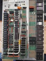
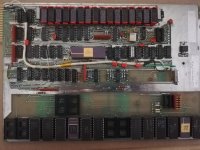
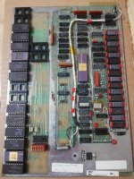
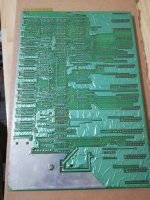
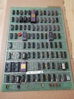
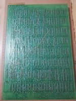
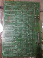
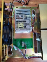
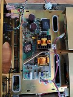
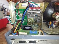
I have attached some miscellaneous images, they are not so good but they are the best I have.
Feel free to DM me if you wish for finer details, I am not able to send DM myself until I make 10 posts.
Unfortunately, when I first tested the power supply the values of 5V, 20V, -20V seemed reasonable enough, thinking that the boards would drop it down to 15v and -15v for RS232. So the boards have been exposed to 20V and -20V.
To make things worse when then there is any load on the 5v it shuts off the 20V and -20V rise to 35V and -35V so the boards have also seen that too.
The -5V would have also gone way out of range -10v or more.So there is a good chance a lot of the system is dead. So I don't know if I will spend the time to try and fix it. I have no knowledge of power supply repair so it would be a very costly and slow process with little chance of success.
I can see that many of the precision metal film resistors have drifted badly out of spec, more than 50%. So I will replace them and see how it goes. If you have your last order of parts and could post them I may go through the work of replacing the caps. I know the precision resistors drive some opamps so they might be the root cause of the overvoltage, if I replace them things might come right. However, this system has no over-voltage protection so I don't trust it that much for the long term. If I make progress with the power supply I may make a new backplane board with some protection. Not that it's likely to help me at this stage.
I have attached some miscellaneous images, they are not so good but they are the best I have.
Feel free to DM me if you wish for finer details, I am not able to send DM myself until I make 10 posts.
Attachments
cliff@swissbay.net
Member
Hello,
I had the same thoughts about the over voltage situation. Try pull some 74 ic and test just to see how many are dead. Should give idea how far it went. Same for the RAM.
I had the same thoughts about the over voltage situation. Try pull some 74 ic and test just to see how many are dead. Should give idea how far it went. Same for the RAM.
ashlin4010
Member
The 5v has been ok, it's the chips on the -12 and +12 that will be dead, same for the RAM. But I don't care much about the RAM anyway.
I don't know what chips use the -12 and +12 but they will be the hardest to replace, I have not yet looked to see what chips use those voltages but I would think most of the chips on the IO board.
The CRT driver may also be damaged but I am less concerned about that.
I will try my best at fixing the power supply, and with some luck, I will get it going. I have some reading to do on power supply design first.
cliff@swissbay.net
Member
Hi, Yes I agree. Once the power supply is working again, another chapter begins
ashlin4010
Member
As I am making a run of PCBs I have made up a power board for the power supply. Kicad files are attached.
BOM is as follows:
1 x https://www.digikey.com/en/products/detail/te-connectivity-amp-connectors/5650118-1/2135730
3 x https://www.digikey.com/en/products/detail/te-connectivity-amp-connectors/63951-1/1130700
2 x https://www.digikey.com/en/products/detail/eaton-electronics-division/BK-1A1907-06-R/954119


Note: This board is untested and may be incorrect.
Warning: This board used mains voltage, extreme care needs to be taken when handling it and the TD830 power supply. Please take the time to fasten it to a secure surface.
BOM is as follows:
1 x https://www.digikey.com/en/products/detail/te-connectivity-amp-connectors/5650118-1/2135730
3 x https://www.digikey.com/en/products/detail/te-connectivity-amp-connectors/63951-1/1130700
2 x https://www.digikey.com/en/products/detail/eaton-electronics-division/BK-1A1907-06-R/954119
Note: This board is untested and may be incorrect.
Warning: This board used mains voltage, extreme care needs to be taken when handling it and the TD830 power supply. Please take the time to fasten it to a secure surface.
Attachments
cliff@swissbay.net
Member
As I am making a run of PCBs I have made up a power board for the power supply. Kicad files are attached.
BOM is as follows:
1 x https://www.digikey.com/en/products/detail/te-connectivity-amp-connectors/5650118-1/2135730
3 x https://www.digikey.com/en/products/detail/te-connectivity-amp-connectors/63951-1/1130700
2 x https://www.digikey.com/en/products/detail/eaton-electronics-division/BK-1A1907-06-R/954119
View attachment 1258541View attachment 1258542
Note: This board is untested and may be incorrect.
Warning: This board used mains voltage, extreme care needs to be taken when handling it and the TD830 power supply. Please take the time to fasten it to a secure surface.
Perfect break-out to test PSU
Excellent and also to test outside the main unit.As I am making a run of PCBs I have made up a power board for the power supply. Kicad files are attached.
BOM is as follows:
1 x https://www.digikey.com/en/products/detail/te-connectivity-amp-connectors/5650118-1/2135730
3 x https://www.digikey.com/en/products/detail/te-connectivity-amp-connectors/63951-1/1130700
2 x https://www.digikey.com/en/products/detail/eaton-electronics-division/BK-1A1907-06-R/954119
View attachment 1258541View attachment 1258542
Note: This board is untested and may be incorrect.
Warning: This board used mains voltage, extreme care needs to be taken when handling it and the TD830 power supply. Please take the time to fasten it to a secure surface.
cliff@swissbay.net
Member
As I am making a run of PCBs I have made up a power board for the power supply. Kicad files are attached.
BOM is as follows:
1 x https://www.digikey.com/en/products/detail/te-connectivity-amp-connectors/5650118-1/2135730
3 x https://www.digikey.com/en/products/detail/te-connectivity-amp-connectors/63951-1/1130700
2 x https://www.digikey.com/en/products/detail/eaton-electronics-division/BK-1A1907-06-R/954119
View attachment 1258541View attachment 1258542
Note: This board is untested and may be incorrect.
Warning: This board used mains voltage, extreme care needs to be taken when handling it and the TD830 power supply. Please take the time to fasten it to a secure surface.
This reminds me of two projects, one for the SuperBrain Jr and the other for Altos 580. Both had power supply issues and fixing was not too obvious. I decided to replace the original power supply with common modern alternatives. Created simple adapter PCB for the original power connectors. Both solutions worked out fine. It was better approach, maybe no longer original, but its works well and safe too.
Alternatively, if your power supply for the TD is beyond saving, maybe you can opt for an alternative power supply. The voltages required are standard, so no issue to source.
Attachments
Bruce Tomlin
Experienced Member
I downloaded that b1.zip the other day. It's 6800 code (you can see the CPU in a photo above), at A000-BFFF and E000-FFFF in 1..8 order. I was able to get most of it to disassemble, but haven't gone into looking at what the code does yet.
However, there seem to be some inconsistencies in b3 (B000) and b5 (E000). Basically, there are jumps and relative branches that point to the middle of instructions or to non-code. These are internal inconsistencies,not external from other segments and some incoming external references too. b3 is particularly suspect because all other chips start with 2 bytes pointing to an address later in the chip, which is followed by what might be a checksum, then a bunch of 3F bytes, but it starts with 1196 when it should probably be B7xx. And its last exact 256 bytes are all 3F, with code flowing right into it. It also has B026: 27C5 BEQ AFED, crossing a chip boundary.
So maybe there's a chance that those two had bit rot or a bad dump. Or maybe I'm just seeing data that looks like code. It would be good if another unit could get dumped someday for comparison.
EDIT: there's a jump table at FD00 with some B5xx references to the middle of instructions
However, there seem to be some inconsistencies in b3 (B000) and b5 (E000). Basically, there are jumps and relative branches that point to the middle of instructions or to non-code. These are internal inconsistencies,
So maybe there's a chance that those two had bit rot or a bad dump. Or maybe I'm just seeing data that looks like code. It would be good if another unit could get dumped someday for comparison.
EDIT: there's a jump table at FD00 with some B5xx references to the middle of instructions
Last edited:
cliff@swissbay.net
Member
Hello There,I downloaded that b1.zip the other day. It's 6800 code (you can see the CPU in a photo above), at A000-BFFF and E000-FFFF in 1..8 order. I was able to get most of it to disassemble, but haven't gone into looking at what the code does yet.
However, there seem to be some inconsistencies in b3 (B000) and b5 (E000). Basically, there are jumps and relative branches that point to the middle of instructions or to non-code. These are internal inconsistencies, not external from other segments. b3 is particularly suspect because all other chips start with 2 bytes pointing to an address later in the chip, which is followed by what might be a checksum, then a bunch of 3F bytes, but it starts with 1196 when it should probably be B7xx. And its last exact 256 bytes are all 3F, with code flowing right into it. It also has B026: 27C5 BEQ AFED, crossing a chip boundary.
So maybe there's a chance that those two had bit rot or a bad dump. Or maybe I'm just seeing data that looks like code. It would be good if another unit could get dumped someday for comparison.
Interesting indeed. I will check the files again to check if I did not introduce any inconsistancies.
Regards,
Cliff
cliff@swissbay.net
Member
Here is a new set. I did not compair with the previous set, so it is what it is.I downloaded that b1.zip the other day. It's 6800 code (you can see the CPU in a photo above), at A000-BFFF and E000-FFFF in 1..8 order. I was able to get most of it to disassemble, but haven't gone into looking at what the code does yet.
However, there seem to be some inconsistencies in b3 (B000) and b5 (E000). Basically, there are jumps and relative branches that point to the middle of instructions or to non-code. These are internal inconsistencies,not external from other segmentsand some incoming external references too. b3 is particularly suspect because all other chips start with 2 bytes pointing to an address later in the chip, which is followed by what might be a checksum, then a bunch of 3F bytes, but it starts with 1196 when it should probably be B7xx. And its last exact 256 bytes are all 3F, with code flowing right into it. It also has B026: 27C5 BEQ AFED, crossing a chip boundary.
So maybe there's a chance that those two had bit rot or a bad dump. Or maybe I'm just seeing data that looks like code. It would be good if another unit could get dumped someday for comparison.
EDIT: there's a jump table at FD00 with some B5xx references to the middle of instructions
Attachments
Bruce Tomlin
Experienced Member
Same CRCs, so it wouldn't be the conversion process.Here is a new set. I did not compair with the previous set, so it is what it is.
cliff@swissbay.net
Member
Same CRCs, so it wouldn't be the conversion process.
I think the ROMS or the dump is the cause of these files being incomplete.
cliff@swissbay.net
Member
It is in the same array so it is probably something similar.
The issue may be that the chip selects are programmable wrt being active high or low.
another terminal was dumped, but the dump doesn't work correctly when someone from the
MAME team tried to run it
I've located a technical manual but I have been unable to reach anyone in Italy who will
reply to me about it.
items
983 AA.VV. DOCUMENTATION PACKAGE - BURROUGHS MACH. LTD. 79/76 U.K. 14/05/98 DONO BURROUGHS EN
984 AA.VV. DOCUMENTATION PACKAGE-BURROUGHS MACH. LTD. 78/80 U.K. 14/05/98 DONO BURROUGHS EN
985 AA.VV. TP31X/323 JOURNAL PRINTERS - BURROUGHS - TEST AND FIELD DOC. + ALTR 79/81 U.S.A. 14/05/98 DONO BURROUGHS EN
986 AA.VV. BURROUGHS ITALIANA S.P.A. - ISTRUZIONI VARIE 14/05/98 DONO EN
987 AA.VV. MT983/993 DISPLAY TERMINALS - TEST AND FIELD DOC. - BURROUGHS Jan-79 U.S.A. 14/05/98 DONO BURROUGHS EN
988 AA.VV. MT983/993 DISPLAY TEST AND FIELD DOCUMENTATION 79/80 U.S.A. 14/05/98 DONO BURROUGHS EN
989 AA.VV. MT983/993 DISPLAY TEST AND FIELD DOCUMENTATION Jan-80 U.S.A. 14/05/98 DONO BURROUGHS EN
990 AA.VV. TP130 - TP133 - TP138 - ALPHA NUMERIC KEYBOARD - F. D. 78/80 U.S.A. 14/05/98 DONO BURROUGHS EN
991 AA.VV. TP110 SERIES ALPHA NUMERIC KEYBOARD - F. D. Jan-79 U.S.A. 14/05/98 DONO BURROUGHS EN
992 AA.VV. DOCUMENTATION PACKAGE - BURROUGHS MACH. LTD - 31800428 BD2-20 PROCE Jan-80 U.S.A. 14/05/98 DONO BURROUGHS EN
993 AA.VV. T&F MODULE FOR THE UNIVERSAL SD2 ASSEMBLY - BURROUGHS Jan-82 U.S.A. 14/05/98 DONO BURROUGHS EN
I could identify 2 ROMS from the link you provided. I have attached zip file with what I could retrieve so far.

Attachments
cliff@swissbay.net
Member
As it happens I acquired one of these terminals yesterday, a TD833 with a REV D CPU board. My initial attempts to dump the ROMs were unsuccessful however I understand where I went wrong and am in the process of making an adaptor so I can read the AM9218s as a 27128, effectively mapping the three CS pins to A11, A12, and A13.
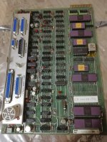
The way the ROMs are generally wired can be seen in the image below.
View attachment 1258464
The address lines and CS lines are common to all ROMs
The 16 ROMs are in two groups of 8 each with a data bus each, a bus is selected via the CPU using some N8T97N (tri-state).
I don't know where the CS lines are derived, however, they can't be directly mapped from the address bus as there is insufficient address space.
Incidentally, it would happen that my power supply is also not working, any load on the 5V rail, and the power supply shutdowns. Cliff if you could possibly provide me with a list of voltages and their location I would appreciate that greatly. I have seen 5v 20v -21V however I don't know if there are more. One of the 5v regulators looks to be shorted to ground too, or perhaps it's just off.
Here is a table of the ROMs this system has.
Slot Chip MAKS label 1 2 3 AM9218BCC 2641-4904 4 CN7640F 2641-4912 5 AM9218BCC 2641-9465 6 CN7214 2639-6838 7 CN7215F 2639-6853 8 CN7216F 2639-6861 9 10 11 CN7217F 2639-6879 12 CN7642F 2641-4938 13 AM9218BCC 2641-4946 14 C48143 2641-4953 15 C48144 2641-4961 16 CN7792F 2641-4979
Here is a link to some of the information have gathered
Burroughs TD833 - Google Drive
drive.google.com
I could see that one of my CPU boards have the exact same ROMS as in your list