Hugo Holden
Veteran Member
can I try putting the ICs back on to see if the signal reappears?
The IC's at the moment have nothing to do with the price of Fish. Because the input signal (video) has gone awry somehow.
No, put the board aside for a while.
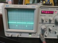
Try to get the video output from the C64 working properly first. Put the pull up resistor to +5V back on the video signal line and see if you can see the video signal on the scope looking normal or not.
Only when the video signal is working normally does the board stand any chance of working.