Witchy
Experienced Member
Hi folks,
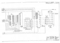
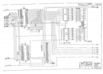
Recently I dug out my B700 high profile, UK edition, and predictably it seemed dead. Probing with a 'scope showed activity though, and the CURSOR pin of the CRTC gave a trace of a flashing cursor so I checked over the video side of things. I could see a raster on the monitor plus H and V sync on the monitor connector but no video. Following the schematic backwards from the monitor pins I discovered a 74LS86 with a dead output; changed that and yay, a display!
Keyboard was good too so I added my PET MicroSD adapter and while I was testing that I heard a crack. I powered off immediately and pulled the MicroSD then inspected everything around the IEEE bus, all looked OK. Tested the PSU for a short and it was OK, so I put a DMM on the 5V rail and powered up again, turns out the crack was the MC1488 RS232 driver chip shorting out so it smoked and my 5V rail disappeared. Testing the PSU again showed +5V and +12V had collapsed to ~1.3V and -12V had disappeared altogether.
The datasheet for the MC1488 shows it takes in +12 and -12 so I suspected I'd had a short between those two rails and it's taken out...something. Testing the components on the output side however showed a failed rectifier diode pair on the 5V rail (marked BVW51-100) so I replaced that and tested all the diodes which were OK. The caps are below spec though so I'll replace those too.
Has anyone worked on these before? The B700/CBM-II 710 seems to be pretty rare these days. The PSU is made by a company called CEAG and thankfully a schematic is on zimmers - http://www.zimmers.net/anonftp/pub/cbm/schematics/computers/b/cbm700-ceag-PSU.jpg
Cheers!


