• Please review our updated Terms and Rules here

CBM Pet 4032 DOA

Do you mean A0 etc. rather than D0 etc. ?

If power is off, address decoding doesn't happen, so what you're seeing is probably normal.

Technically you can't measure continuity when the power is on. You can only see similar values. The address decoding logic asserts similar values, but doesn't cause 'switch closure'.

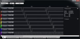
What is connected to channel 5 of your analyser in that picture? Something doesn't look right there.
 
yes I kind of guessed it was ok , my initial rush of excitement faded quickly :)

UD6
pins 9,10,12,13,124,15 & 20

but its a wild goose chase I think

im not sure what was on 5 , ive disconnected it all, UD8 I think . however it compares exactly to a working 4032
 
however with the eprom kernel in and power on - I'm getting continuity on the following addresses.

UD6
9-D0
10-D1
12-GND
13-D3
14-D4
15-D5
20-Sel f

now is this normal with power on ? , with the power off i don't get any continuity at all on those lines?

You are losing me, what addresses? I hope you are not doing continuity (Ohm) checks with power on? Or what do you mean by 'continuity'?

Also, those pins on the ROMs should be connected to those signals, shouldn't they? You may need to go a littler slower so we can follow your work/methodology.
 
with the NOP in same again (with no roms fitted)

Mike,
Did you make the NOP Generator correctly? If the NOP Generator is made correctly, you do not have to remove ROM and RAM. The eight data lines on the board should NOT connect to the CPU data lines. the CPU data lines are hard wired to a $EA (NOP) pattern on the top 6502 socket (NOP socket), but the eight lines do not connect to the bottom socket. While the CPU is happily running NOPs, the ROMs and RAMs are just as happy outputting their data when SELECTED without conflict on the data bus.
-Dave
 
Last edited:
Hi Dave

Yes i did but only by accident i didn't know the power was on...oops

Luckily all is well , its working just as before or not as the case maybe.

I might have a rom replacement tomorrow , I'm interested to see if the roms fully replaced would solve this little problem

I've checked the rom addresses with the logic analyser (rom to cpu) and all are good.

The SEL lines are good except for UD12 but thats an original socket so i expect bad connection , not sure yet

I really don't know what else to check
 
hi Dave

yes i have the eight address lifted and not connected thru the socket, can it be run with rom in ok? i might try that and see if there is a difference ?

I copied this NOP example is this correct ? All the address are active and busily chatting away
 

Attachments

  • nop.jpg
    nop.jpg
    35.4 KB · Views: 1
Last edited:
I can't see the picture, but, hoping you have $EA NOP instead of $E8 INX.

Actually, it wouldn't matter much.
 
$EA is 11101010 and $E8 is 11101000. It shouldn't matter though (I'm apparently slow today) because they both do the same thing from your point of view. The difference is internal to the CPU.

NOP causes "nothing" to happen and the PC register to increment (address lines).

INX causes the X register to increment, and the status register updates, and then the PC register is incremented.

To get $EA, D0, D2, and D4 are tied to ground; and D1, D3, D5, D6, and D7 are tied to +5V.
 
On side note - i have a key missing on the PET , 1980 4032 PET keyboard not the business one.

i have the key but not the mechanism ... is it the same as another ? Vic20 or what ever?
 
On side note - i have a key missing on the PET , 1980 4032 PET keyboard not the business one.

i have the key but not the mechanism ... is it the same as another ? Vic20 or what ever?

Sadly, no the keys are different from the VIC20 and the C64 except for the very earliest VIC20's I believe.
 
That could be tricky then. I wonder if the keyboard was used in other things , Mitsumi was it ? Or did they make the c64 or was it Amiga keyboard. I'll have to look at my pics when I stripped down the keyboard I don't remember seeing a name though or label on it.
 
attachment.php

The SEL E with the 'glitch' in the middle is correct (see Channel 5). That select line is intentionally disabled when the signal x8xx is set to allow the I/O addresses to work. The I/O uses the $E8XX memory space so the system cannot have the E ROM active when the I/O is being selected (PIA or VIA or CRTC).

Everything is panning out properly so we must be close to getting the PET to work. Did you check the address lines at the RAM chips? They are quite complicated as they go through tri-state buffers and are strobed into RAM chips with column and row pulses. Take your time and look so something open or 'funny looking'. I assume you checked the -5V and +12V at the RAMs besides the +5V with your voltmeter? Concentrate only on the Lower Address block (the eight odd numbered RAM chips) as those are needed to boot.
 

Attachments

  • correctroms-2.jpg
    correctroms-2.jpg
    97 KB · Views: 1
I haven't spent much time on the ram to be honest I focused on the roms. How much ram does pet tester scan for defects ? It does occasionally pick up a few b instead of g in its scan but usually these are in the first few scans of the ram and then they disappear and the screen is full of gggggg's

Initially I checked all the ram for power and ground but I haven't put the logic tester on the ram. I should be able to pin down the general area of the fault later today....

Would a ram addressing fault stop the booting sequence ?

I have externally tested both video ram and system ram and it (visually,I.e the test system boots) checks out. I have not run interrogation software to check it, perhaps I should.

Currently the pet chirps, flashes a jumbled screen and then clears it to a blank screen. No Ready or Commodore bytes free.

I could program a ram testing rom to interigate the 4116 and 2114 in another machine...I may do that this morning.
Mike.

Update:

The plug in ram and rom board has arrived and now i have a working PET. If i select system rom and ram - it will not boot but lower ram is working fine giving 16k of free ram but the rom selection stopes the pet dead. So i have a ROM or rom related problem still to fix.


however if i select just the ram/rom board settings and ignore the PET ram & rom it boots just fine.

mike.

http://youtu.be/GAfVCoTNM98
 

Attachments

  • IMG_3510.jpg
    IMG_3510.jpg
    60.1 KB · Views: 1
  • IMG_3511.jpg
    IMG_3511.jpg
    94.9 KB · Views: 2
  • IMG_3512.jpg
    IMG_3512.jpg
    33.6 KB · Views: 1
  • IMG_3517.jpg
    IMG_3517.jpg
    69.8 KB · Views: 1
  • IMG_3518.jpg
    IMG_3518.jpg
    103.4 KB · Views: 1
Last edited:
The plug in ram and rom board has arrived and now i have a working PET. If i select system rom and ram - it will not boot but lower ram is working fine giving 16k of free ram but the rom selection stopes the pet dead. So i have a ROM or rom related problem still to fix.

Mike,
This is great. You can stop here or since you used the RAM/ROM board to isolate the problem mainly to the ROM area, you can continue the troubleshooting. Somewhere there is probably a bad connection in the UD6 to UD8 area. We now know the data bus on the main board is OK as the I/O chips are working.

You have done a great job and learned more about the PET than you probably ever wanted to know! If you continue troubleshooting, we will be glad to help.
-Dave
 
Hi Dave

thank you , I've enjoyed it but its been a pig of a job. The pet doesn't help much does it.

i will ultimately have it running on its own but for the moment that will do ....i won't be beaten :). I was under the impression that this pet was put away working in the early 80s - however thats not true on my travels I've found dead chips, missing capacitor, leaking capacitor and a burnt track.

i next project is the CRT and a .tap module for it so i can load some things. Ive had to strip and repair the 2CN for it this after and I've partially recapped the CRT video board as not all my parts arrived.

And anyway I've almost worked thru the board changing every part :)

i have a few more pics to put on.

thanks again Dave.

PS.

Should the writing on the CRT be more to the left of the screen?
 
I've checked by writing characters along the screen and its not far off to be honest. The screen still has the wobbly image and doesn't like being adjusted to full size.

im not sure but i suspect a lack of power or ripple some where , hopefully a full cap change and a check over fill find the fault.
 
Back
Top