| VCF West | Aug 01 - 02 2025, | CHM, Mountain View, CA |
| VCF Midwest | Sep 13 - 14 2025, | Schaumburg, IL |
| VCF Montreal | Jan 24 - 25, 2026, | RMC Saint Jean, Montreal, Canada |
| VCF SoCal | Feb 14 - 15, 2026, | Hotel Fera, Orange CA |
| VCF Southwest | May 29 - 31, 2026, | Westin Dallas Fort Worth Airport |
| VCF Southeast | June, 2026 | Atlanta, GA |
-
Please review our updated Terms and Rules here
You are using an out of date browser. It may not display this or other websites correctly.
You should upgrade or use an alternative browser.
You should upgrade or use an alternative browser.
CBM PET 710 WITH BASIC PROBLEMS
- Thread starter Desperado
- Start date
Eudimorphodon
Veteran Member
the strange thing is that before I deleted the EPROMs, I had a screen...
The CBM-II uses a 6845 CRTC chip to generate the screen refresh, and said chip needs to be initialized by the CPU before it will drive the signals correctly. So, well, the fact that the screen was working before you destroyed the original contents of the ROMs is proof, well, they at least *had* the correct software on them.
I guess I’m pretty confused what lead you to blowing them away, if the machine was successfully getting you to a BASIC prompt. There are a lot of other things that seem more likely for this situation.
Eudimorphodon
Veteran Member
… The thing that would worry me about a machine as rare as a B710 is there may well be differences between individual machines that needed software tweaks to deal with; the fact that it had EPROMs instead of mask ROMs in it is a really bad sign.
daver2
10k Member
What we were going to check was whether the EPROMs had the 'correct' contents by comparing them to the downloaded files, or whether a bit of 'bit rot' had occured.
However, the OP took that to mean erase the EPROMs and burn new contents...
I wanted to rule out that some corruption had occurred that caused the machine to boot up correctly, but go faulty when a <RETURN> was pressed.
However, if they were 'bespoke' EPROMs, this would identify the differences...
Unfortunately, they have now been destroyed...
Dave
Eudimorphodon
Veteran Member
Reading the manuals for the B-series I gotta say, these are *weird* machines. Not much like a normal PET at all…
If I’m understanding this right these machines have 2K of SRAM in CPU bank 15, which is where the ROMs and I/O live, that BASIC basically entirely runs in; the zero page is there, as is all the housekeeping variables, etc. All the DRAM is used for is the basic program text, variables, whatever. I wonder if the initial problem was a DRAM issue; it booted fine because all of that lives in the SRAM, but it wanders off into the weeds when a keypress makes it want to do something in DRAM?
If I’m understanding this right these machines have 2K of SRAM in CPU bank 15, which is where the ROMs and I/O live, that BASIC basically entirely runs in; the zero page is there, as is all the housekeeping variables, etc. All the DRAM is used for is the basic program text, variables, whatever. I wonder if the initial problem was a DRAM issue; it booted fine because all of that lives in the SRAM, but it wanders off into the weeds when a keypress makes it want to do something in DRAM?
Eudimorphodon
Veteran Member
... Anyway, I guess what's done is done. The ROM chips looked like they were on a daughterboard of some sort? Are you absolutely positive that's seated correctly? (How does it connect to the board underneath? The schematics sheet on Zimmers seems to say the MASK ROM sockets under it are the 24 pin variety, while the EPROMS are of course 28 pins. Does it plug into a single socket for most of the lines and have single pins going to the other chip selects? Maybe it's just loose from messing with it.)
Hugo Holden
Veteran Member
Desperado; One thing you can do in the future, if you are wanting to read the contents of a vintage UVEPROM, without any risk of damaging it, unintentionally with an unwanted programming event, is to make an adapter socket for it, and tie the IC's programming pin so that the IC cannot get programmed regardless if the programmer tries to do that.
I often do this, just in case I do something silly with the software, like accidentally hitting the programming button by mistake, or my mouse falls off the bench and the unthinkable happens. It also allows for any faults in a programmer, but they are not very likely. Still you can never be too cautious.
Vintage ROM code is precious and it pays to preserve it at all costs. We don't really know what % of vintage ROMs from the World's vintage computers & peripherals have been dumped, a lot probably, but not all, and if the dumps are 100% accurate and if there are deliberate variations or mods to the code, either by a manufacturer, or even a past owner. So any code that can be retrieved and saved from vintage ROMs, is always worth the effort.
daver2
10k Member
It also pays (if possible) to set your EPROM programmer up to perform a BLANK CHECK before programming and a VERIFY check after programming.
That way, if the EPROM is not blank to start with, the programmer should not program it.
Dave
That way, if the EPROM is not blank to start with, the programmer should not program it.
Dave
Desperado
Veteran Member
- Joined
- Nov 25, 2017
- Messages
- 7,880
yes exactly, the adapter is only connected to the central socket of the three roms, then there are some wires that go to the motherboard. It connected well to the center socket.... Anyway, I guess what's done is done. The ROM chips looked like they were on a daughterboard of some sort? Are you absolutely positive that's seated correctly? (How does it connect to the board underneath? The schematics sheet on Zimmers seems to say the MASK ROM sockets under it are the 24 pin variety, while the EPROMS are of course 28 pins. Does it plug into a single socket for most of the lines and have single pins going to the other chip selects? Maybe it's just loose from messing with it.)
Attachments
Those are not 128k EPROMs... (https://www.elnec.com/en/device/Hitachi/HN482764/) and what model of programmer did you use to program them?
Desperado
Veteran Member
- Joined
- Nov 25, 2017
- Messages
- 7,880
Yes these are 64K eprom, i used a GQ 4x programmerThose are not 128k EPROMs... (https://www.elnec.com/en/device/Hitachi/HN482764/) and what model of programmer did you use to program them?
daver2
10k Member
I think the 128k printed on the label refers to the amount of RAM in the machine as opposed to the size of the EPROM.
When you say "It connected well to the center socket." how do you actually know? Have you tested it with a multimeter?
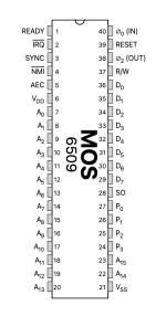
When you turn the machine on (and immediately after a RESET condition) do you observe CPU SYNC pulses and then they stop?
Dave
When you say "It connected well to the center socket." how do you actually know? Have you tested it with a multimeter?
When you turn the machine on (and immediately after a RESET condition) do you observe CPU SYNC pulses and then they stop?
Dave
Desperado
Veteran Member
- Joined
- Nov 25, 2017
- Messages
- 7,880
unfortunately notWhen you say "It connected well to the center socket." how do you actually know? Have you tested it with a multimeter?

no i have always 0V signal and not waveform signal on pin 3.When you turn the machine on (and immediately after a RESET condition) do you observe CPU SYNC pulses and then they stop?
Attachments
daver2
10k Member
But how are you testing it?
If we keep giving you things to try, and you don't do them properly, then how do you expect us to keep helping you? The only way you know for sure that something is making good contact is to test it - not just look at it!
Dave
If we keep giving you things to try, and you don't do them properly, then how do you expect us to keep helping you? The only way you know for sure that something is making good contact is to test it - not just look at it!
Dave
Desperado
Veteran Member
- Joined
- Nov 25, 2017
- Messages
- 7,880
Scope probe on pin 3 DaveBut how are you testing it?
Dave
daver2
10k Member
But, on a power up or reset condition, the signal will be there for only a short period of time. How are you detecting this if it only lasts (say) 1 millisecond?
Dave
Dave
Desperado
Veteran Member
- Joined
- Nov 25, 2017
- Messages
- 7,880
in this case then I will have to use the logic probe!But, on a power up or reset condition, the signal will be there for only a short period of time. How are you detecting this if it only lasts (say) 1 millisecond?
Dave
daver2
10k Member
If you don't see anything when you press reset, is the reset button a hard reset or a soft reset?
If you monitor the reset pin of the CPU, when you press the reset button do you see any actual activity on the reset pin of the CPU or not?
If you do, and you do not see any activity on the CPU SYNC pin, then the CPU is not even starting up.
I did ask you a while ago to check the power rails and the clock signal, but you did not do what I asked you to do...
Dave
Desperado
Veteran Member
- Joined
- Nov 25, 2017
- Messages
- 7,880
unfortunately I don't know how to give you an answer...If you don't see anything when you press reset, is the reset button a hard reset or a soft reset?
Yes! if i probe cpu pin 39 and i press reset i see the signal which goes low and then stay highIf you monitor the reset pin of the CPU, when you press the reset button do you see any actual activity on the reset pin of the CPU or not?
yes i checked sync signal on cpu...I did ask you a while ago to check the power rails and the clock signal, but you did not do what I asked you to do...