• Please review our updated Terms and Rules here

CBM PET 710 WITH BASIC PROBLEMS

I stopped at A7 cause wave forms was too bad

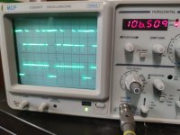
To be clear: I actually don’t think those waveforms are as bad as you think they are. In fact, the more I look at them the more I think the NOP ROM probably is running, at least in the cases where you have SYNC and constant pulses on the kernel eprom select. The difference between the shots of A0 and A1 look like I would expect, IE, you’ve got a double width wave on A1 than A0, but because the pulse train you get from the NOP ROM isn’t 100% regular your scope is refusing to lock properly and displaying this trash waveform as the pattern “rolls” horizontally.

We tried this earlier, I think, but can we try again? Attach the probe with the trigger enabled to A12, set your period to the fastest setting, and see if *that* can give you the stable square wave when you put the non-trigger probe on A0. (Verify A12 is pulsing first.) The only thing you care about seeing on the trace from the trigger probe is the initial rise/fall off the trigger itself, it should be a flat line at the div/sec setting we need on the other probe.

Edit: make sure the trigger is specifically set for “edge”, the slope (rising/falling) shouldn’t matter. Try both.
 
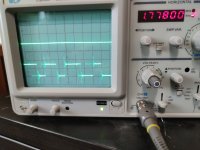
This is trigger probe on A12
 

Attachments

  • 1711794783598..jpg
    1711794783598..jpg
    1.2 MB · Views: 5
Why do you expect to see a perfect waveform?

You will only see a perfect waveform under the conditions of a PET NOP generator. The PET NOP generator ALWAYS causes the CPU to execute NOP instructions.

This NOP generator cannot do that. We have to code up a JUMP at the end of the EPROM to jump back to the start of the EPROM.

As a result, the address line waveforms will be imperfect.

It takes longer to execute a JUMP instruction than a NOP instruction, so the address lines will 'shift' a bit when it gets to the end of the EPROM.

You only get 'perfect' waveforms with hardware clocks that are free running and software loops that are perfect in themselves.

Dave
 
This is A0 , with trigger on A12 in the bottom
 

Attachments

  • 1711806238729..jpg
    1711806238729..jpg
    1.2 MB · Views: 6
We now need to wait for Eudi's analysis before proceeding...

We have stated before that we CANNOT use a 'real' NOP generator on the 6509 CPU because of the two special registers that are at addresses 0000 and 0001 of the CPU itself.

Now, it is just possible that it will work if we try it, but this is the 'suck it and see' method and STILL comes with no absolute guarantee of success when we try it.

However, this wouldn't stop me from trying, but I wouldn't get desparate if it didn't actually work...

It would just confirm in practice what we suspected in theory. But, looking on the bright side, it may work.

Dave
 
We now need to wait for Eudi's analysis before proceeding...

Honestly, these traces are making me feel like I’ve been taking crazy pills. If I had any compatible ROMs at hand I’d be tempted to make a NOP ROM for my PET and see if I could get a decent trace off it, because this still feels like something is wrong with the triggering here. Putting the trigger on the highest address line *should* give you a reliable timebase; that is a reference that will complete a full cycle once per iteration, and regardless of whether you triggered on the high or low slope the instructions following that transition will consistently be 2-cycle NOPs. (Over 4000 of them after each transition.)

I chucked out the idea earlier of building a single-stepper, that’s sounding less dumb to me.
 
@Desperado are you adjusting the trigger LEVEL so that the oscilloscope is really triggering on the trigger waveform or not?

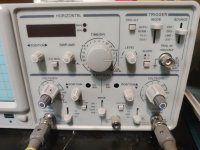
In fact, post a (readable) photograph of the front settings of your oscilloscope - all of them.

Dave
 
Can you post a link to the oscilloscope manual again please?

Is the ALT/CHOP button IN or OUT?

Is the TRIG.ALT button IN or OUT?

Dave
 
Back
Top