• Please review our updated Terms and Rules here

Cheapo IDE interface for Model 4p running MM CP/M

Frank, you do good work for a flyboy (lol). I've been following this thread for some time and it almost makes me want to put my 1000SX on the shelf and jump into a III/IV project. Problem is I'm fast running out of storage space.

Tom D, USN(Ret)
 
Oh a Squid Huh...LoL another fellow Vet didn't know you were Navy there Tom. I salute you for being such. And all Vets for that matter.

I was actually a Electronics tech while in the AF. Forgot a lot of it though. Age and such.

Frank G USAF(ret)

Sorry folks drifted off topic. Yeah AO got out get yourself a model 4. There fun to play with.
 
USB header layout is as-yet untested - if using the mini-USB header, I'd suggest placing that component first then checking the volts appear on the correct rails

Just a quick update - I confirmed the USB header is correctly laid out and operating as expected. Some flux is needed to solder this part however.
 
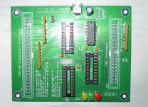
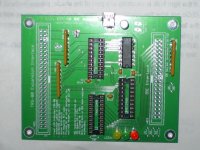
I've built two boards - see image here. Asking £25 each including delivery; please PM if interested. Note that I have no way to test these since I don't have a TRS-80 machine.
 
Frank, you do good work for a flyboy (lol). I've been following this thread for some time and it almost makes me want to put my 1000SX on the shelf and jump into a III/IV project. Problem is I'm fast running out of storage space.

Tom D, USN(Ret)

Always thought it was 'Airdale'... :p

FC2(1107)
:D
 
According to my brother-in-law, my board has arrived. Just waiting for all the parts to get here. But, I have sockets, and some of the discrete parts in my parts box. I've been in the hospital for the past week, so it's going to be a week or more till I get to building mine up. Looking forward to it!
 
Mine arrived today as well. Can't wait to see it running because I have a small but aging collection of smallish IDE hard drives to put to use.
 
Any size should be fine. In the IBM PC, one supporting multi-sector transfers will be faster, like SanDisk Ultra II, but really that's not important.

The TRS-80 disk images and source are all available for download now here.

Good luck with the build!
 
I had all the parts but the two connectors and the resistors. So, this is as far as I got today.

I had soldered the USB connector on, and saw one pin had popped out. It was the fracking ground pin. I think I got it soldered in, I'll have to check it before powering up the board.

One of the holes on RN2 (third from the bottom) was not open. It was easy to open up, so no problem. It was plugged with solder.

If the LED holes were spaced just a bit wider apart, it would be better. Meaning each set of two holes having a little more room between them.

I didn't have 14-pin sockets, so I soldered that one chip to the board. I'll have to get some for the next board.

Like the CF board, this was a snap to assemble. I hope you develop a Model I version soon. Let me know when I can order another board for my Model III.

PB030002.jpg

PB030006.jpg
 
Last edited:
I had soldered the USB connector on, and saw one pin had popped out. It was the fracking ground pin.

That may not be a problem since the shield is also grounded. It depends what the charger is doing with the shield.

If the LED holes were spaced just a bit wider apart, it would be better.

The six LED holes are spaced for a single 6-pin header (see image here) - I was assuming the board would generally go into some kind of project box with the HDD/CF media also, hence LEDs mounted in the case and attached to the board via the header. But, since both assemblers have requested direct placement, I it makes sense to make that change. Of course, three separate 2-pin headers could always then be used instead.

I hope you develop a Model I version soon.

Does anyone know what exactly needs to be done to make that possible? Since the interface is fully buffered, it should already have electrical compatibility, by my understanding (with the expansion box, that is).
 
Back
Top