• Please review our updated Terms and Rules here

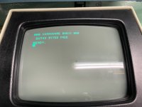
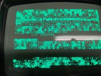
Commodore 3016 scrambled screen

I would count the number of 'rubbish' bytes in the block and then the number of good bytes. I am guessing they will be a power of 2.

I would then look at the CPU address lines, the buffeted address lines, the video RAM address multiplexers and the address lines to the video RAM. It will be one of these. Knowing in advance which address line it is will reduce the search time...

Dave
 
So what you mean is start with adress line which i most logic one?
AB2?
No.

I count 3 lines of 40 characters + 8 on the next line of rubbish = 128 = $7F.

Writing to video address 0 actually writes to video address 128. Or (in hex) $0000 writes to $0080.

I therefore suspect AB7, BA7 or SA7 is to blame somewhere.

Dave
 
Last edited:
Just looking back at the historical posts I think you are chasing a couple of problems.

One is an address fault, causing the messages to appear correctly - but in the wrong place.

The other is a data fault, causing an incorrect character to appear where it should (C changed to a B for example).

Of course, you could get both faults simultaneously...

Dave
 
At this moment i can’t find any interruption on Ab7/ba7 or sa7
But my diagnostic clip also display something about a7
5A7B23FE-0D1F-48A5-91C0-8564467B9713.jpeg

This screen is when I try to activate the diagnostic clip
 
So, the problem is with A7 somewhere...

That wasn't a bad guess on my behalf...

I see the diagnostic clip is also displaying 128 bytes of random rubbish at the beginning of the screen.

How many IC sockets have you got in the system and are any of them not functioning correctly?

Dave
 
I found that IC F3 was suspicious. Was also some corrosion on it. I replaced this one and now i have normal screen again.

I continued with post #317 for the IEEE488 port.
First POKE and PEEK with value 0 then with 255.

I meassured every PIN on A7/A8/A9

PINDA7DA7DA8DA8DA9DA9
POKE
0​
255​
0​
255​
0​
255​
1​
5​
0​
0​
5​
5​
5​
2​
0​
0​
0​
3,3​
3,3​
3,3​
3​
0​
0​
0​
4,2​
4​
4,2​
4​
0​
0​
0​
0​
0​
0​
5​
0​
4,5​
0​
4,1​
5​
5​
6​
2,57​
0​
0​
3,2​
3,2​
3,2​
7​
4,5​
4,3​
0​
5,4​
5​
5​
8​
0​
0​
0​
0​
0​
0​
9​
5​
5​
0​
5​
5​
5​
10​
2,5​
2,6​
0​
3,2​
3,2​
3,2​
11​
0​
4,19​
0​
4,2​
5​
5​
12​
0​
0​
0​
0​
0​
0​
13​
0​
4,2​
0​
4,2​
5​
5​
14​
4​
4,1​
0​
3,3​
3,3​
3,3​
15​
5​
5​
0​
5​
5​
5​
16​
5​
5​
5​
5​
5​
5​
 
I will take a look after I have been fed. Just arrived at the hotel on a business trip.

There are a few strange looking voltages there I see though...

Dave
 
DA9 is the IEEE488 control line buffer and wasn't tested with the POKEs. However, the voltages are consistent with the input signal states.

DA7 looks bust - but there is also an input anomaly.

DA8 looks fine though.

The input pins are 3, 5, 11 and 13. These pins should be LOW when you POKE 0 and HIGH when you POKE 255.

This is not true for DA7 pin 3. This pin is LOW on both occasions. Either the chip driving DA7 pin 3 is broken, something is pulling this line LOW, or there has been a measurement error.

The bus pins are 2, 6, 10 and 14. These should follow the input pins. This is not true for pins 6, 10 or 14. We can't tell anything about pin 2 of course.

The readback pins are 1, 7, 9 and 15. These should follow the bus pins. This is not true for pins 1 or 7.

This leads me to believe DA7 is largely duff, but with the caveat regarding input pin 3.

DA8 seems to follow the pattern correctly - so I am not sure why the test fails these data bits (0..3) unless the interface chip is faulty (or the PCB tracks/sockets are faulty)

Dave
 
Last edited:
Finally i received my new IC's. A7 and A8 where defect. After replacement all checks are OK now.
So now i have fully working 3032 ;)
Thanx all for your're help.
Next project is my 3040 drive. I see there is already a thread running for that one.
So i first check that thread .
 
I have one little thing i want to mention.
When i turn the CBM off, you see a bright dot what is burning into the CRT.
In the middle of the screen you now see a black spot caused by the 'dot'

 
If a 220uF does not completely suppress the spot, you can go a to a 330uF. If that didn't fully suppress the bright turn-off spot appearing, then there must be something else wrong, because it keeps the CRT grid negative for a long time after turn-off as it discharges into the 100k brightness potentiometer. Make sure the capacitor is installed properly, with the positive terminal to ground/common. Also try turning the brightness control to be minimum seen on the screen before the set is turned off and see if that makes any difference ?

Unfortunately the dark spot, due to damaged screen phosphor, cannot be fixed once it has occurred.

Interestingly, looking at your video, the effect you have is different than the usual "late" turn-off spot, which appears centrally, often some seconds after the set is turned off. In the case of your set, the effect is immediate at turn off. Suggesting that at that moment the conditions are different than the typical Pet VDU, with the video voltage level at the CRT cathode going quickly low or the rate at which the power supply voltage is collapsing in the VDU being very rapid, which could explain why altering the capacitor to 220uF had no effect for you problem.

In these VDU's there can be an early and a late turn off spot. In the video from Adrian's digital basement, he found that some PET VDU's had a damaged 33v Zener (CR7) in the power supply to the stage that drives the CRT cathode. It had been over-run past its 1W rating in some PET's and developed leakage aggravating the turn-off spot problem. It might pay to replace this Zener and or the filter electrolytic on the video output stage power rail(C27), just in case either of those parts were defective. Though I think only the early version of the 9" VDU has this zener. I think commodore increased the value of R5 from 1.5k to 1.8k or 2.2k to lower the zener power dissipation, But I don't have the notes for that on hand and would need to check that.

A quick calculation shows that the zener dissipation with the 1.5k resistor is 1.14 Watts.
 
Last edited:
I replaced the 33v Zener but no change.
What's the minimal voltage i should use for C22?
I only have 330uF/50v at the moment
Probably ok to use a 50V part, unless the unit has been modified for a higher voltage on the brightness control.

I'm thinking though that what I'm seeing represents the power supply collapsing very rapidly at turn off. Did you check C27? Is the main filter capacitor C1 ok ?

Of the PET VDU's I have seen (unmodified), at turn off the beam appears to be quickly blanked and only appeared later when the negative voltage in the grid circuit depleted as C22 discharged into the brightness control. With your VDU at turn off, immediately, there is still high beam energy (high beam current) and as the H & V scan collapses all of it gets focused in a flash where that damaged area of phosphor is.

It could also be that the video voltage from the computer board , in the turn off process, is switching on the beam.

It would be worth plugging the VDU onto another computer board to confirm the problem resides in the VDU only.

Is it a standard power supply system where the transformer supplying the computer board is the same one supplying the VDU ?

If you turn the brightness control to minimum two questions:

1) does the effect get less or go away at turn off ?
2) with the unit running, and with the brightness control set for min brightness, is it able to cut off the beam, or is the text still quite bright ?
Checked C1 and C27 both ok. Replaced C22 by 330uF but no effect.
Brightness has no effect.
It's standard power supply.
With other mainboard same effect.
 
Back
Top