• Please review our updated Terms and Rules here

Commodore PET 2001-8 stuck on garbled screen

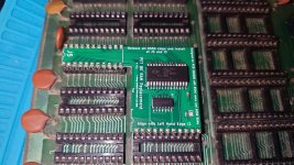
New buffers have arrived and I decided to take the plunge and bought a video ram, system ram module and a character rom set from Nivag Swerdna.
This would help remove all doubt about my existing rams and character set.
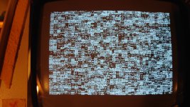
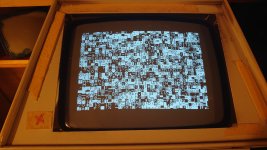
I am yet to replace the buffers, but in trying out the video ram from him I am now getting the following random characters on my vdu, yay!.
I also get the same result with with my other substitute character set so I know that works. So there must be a problem with the substitute rams I bought to use as video ram. 🤔
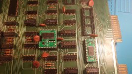
Next thing to do is remove buffers G5 and G6, socket and fit new ones and see what happens.
 

Attachments

  • DSC_1667.JPG
    DSC_1667.JPG
    3.1 MB · Views: 8
  • DSC_1664.JPG
    DSC_1664.JPG
    4.4 MB · Views: 12
That looks much more like the familiar garbled screen PET owners know and love. So that narrows it down to the CPU, the reset circuit, the address decoding, the buffers, the RAM or the ROM. ;)

With the diagnostic ROM in H7, and a known good CPU (it NOPped before so probably good)... I would suspect G5/G6.... if it's not that it's likely to be decoding... or a very long shot the muxes in the video section.

PS
You could re-test the old original Character Generator ROM? ... it might have been good? You could also retry the Tynemouth ROM/RAM board... it won't work if you have G5/G6 issues but it might for some decoding issues.
 
Last edited:
That looks much more like the familiar garbled screen PET owners know and love. So that narrows it down to the CPU, the reset circuit, the address decoding, the buffers, the RAM or the ROM. ;)

With the diagnostic ROM in H7, and a known good CPU (it NOPped before so probably good)... I would suspect G5/G6.... if it's not that it's likely to be decoding... or a very long shot the muxes in the video section.

PS
You could re-test the old original Character Generator ROM? ... it might have been good? You could also retry the Tynemouth ROM/RAM board... it won't work if you have G5/G6 issues but it might for some decoding issues.
G5 and G6 replaced no change. At first there was flickering lines on some of the characters but after reseating new G5 G6 back to steady characters.
No change with Tynemouth board. I can't seem to get eyes on my original character rom.
I have your 8k ram module installed now.
 

Attachments

  • DSC_1674.JPG
    DSC_1674.JPG
    4.7 MB · Views: 13
Probably not helpful but.... testing 2114s is something I tripped myself up on (you shouldn't have a problem in a C64)... 2114 really do use TTL levels so you can get very spurious results if you use something like an Arduino or any modern CMOS uP for that matter since the levels don't quite line up. Always read the small print of your chip tester! I almost junked a pile of 2114s thinking they were fake/broken before realising my mistake.
I had exactly the same issue with 4116's, I bought a tester and it reported faster parts as faulty, but they are not.

Probably the best tester is the PET computer itself and probably, testers should be regarded as screening tools for gross abnormalities. For example, I think to properly check DRAM it needs to be done with various patterns of data and long time lapses in between to check refresh functions and adjacent cell interference. This is why I made the hardware adapter and firmware programs for the PET to do a thorough DRAM test. The inner workings of the 4116 IC are extremely complicated compared to many logic IC's, for something that looks simple from the outside.

But I can say this about specific testers & my experience with them :

This tester produces results on 4116 testing that match the PET and I think it is a very good product:


And so far this 2114 tester has served me well too, but I have less experience with it than the 4116 tester:

 
Last edited:
That's what I was thinking.
It is a long thread and I could not recall when it was checked.

I think when the reset circuit stops, if it does, the likely cause is the 1uF Tant timing capacitor, as the NE555 IC is much more reliable than a Tant capacitor. But the reset timer could also be working and it not make it through some buffers to get to the CPU. So if it is a reset issue, those need checking too. But there could be other reasons why the CPU is not executing code, address decoding, buffers ROM, RAM etc as Nivag says. I think the NOP generator testing was ok.
 
FYI The RAM board looks like it has been damaged. Please take a closer photo to confirm; maybe its just a trick of the light.
 
Last edited:
FYI The RAM board looks like it has been damaged. Please take a closer photo to confirm; maybe its just a trick of the light.
Didn't notice any damage. I will look again when I'm near it. Only thing that did happen when I first plugged it in was alot of noise over the characters, but after a couple of power cycles it cleared. I think it was the board screaming I don't want new ram. 😆
 
It is a long thread and I could not recall when it was checked.

I think when the reset circuit stops, if it does, the likely cause is the 1uF Tant timing capacitor, as the NE555 IC is much more reliable than a Tant capacitor. But the reset timer could also be working and it not make it through some buffers to get to the CPU. So if it is a reset issue, those need checking too. But there could be other reasons why the CPU is not executing code, address decoding, buffers ROM, RAM etc as Nivag says. I think the NOP generator testing was ok.
Yes I have heard those little tants can go pop. But now I think about it we did test the reset more than once. But it could have failed since.
I will check it again.
 
Looks ok. Think that cap was close in previous pic.
My mistake, all looks good.

I would continue with the socketing of the buffers. Once that is done we can divide and conquer.

Feel free to retest anything but it will be much simpler once we can isolate the different parts of the buffered data bus.

You have changed quite a few things now... We should do some continuity checks once all the buffers are socketed.
New buffers in place. So all 6 are new and socketed. No change. Just tested with nop and reset working and a flashing activity led.
 

Attachments

  • DSC_1686.JPG
    DSC_1686.JPG
    5.3 MB · Views: 2
New buffers in place. So all 6 are new and socketed. No change. Just tested with nop and reset working and a flashing activity led.
OK. So let's see if the CPU can run PETESTER

Remove the NOPPer... Put a 6502 in the CPU socket.

Install the H7 Diagnostic ROM

Turn it on... Now check with a logic probe on the pins of the ROM

Is there activity in the data and address pins? All of them? Some of them.

Then go to the CPU and ensure you have activity on the corresponding pins
Ok H7 in place with CPU and I am still getting that interference with H7 tester that I got when I first tried it before renewing all the buffers. Or is this normal?
 

Attachments

  • DSC_1689.JPG
    DSC_1689.JPG
    3.9 MB · Views: 9
  • _20230105_200553.JPG
    _20230105_200553.JPG
    2.8 MB · Views: 8
OK That's interesting.

With all Buffers REMOVED

EXPERIMENT 1:

Can you leave the ROM in but remove the CPU and tell me what you see.

EXPERIMENT 2:

Can you leave the ROM in but put in the NOPPER and CPU and tell me what you see
 
Back
Top