- VCF South West - June 14 - 16, Davidson-Gundy Alumni Center at University of Texas at Dallas
- VCF West - Aug 2 - 3, Computer History Museum, Mountain View, CA
- VCF Midwest - Sept 7 - 8 2024, Schaumburg, IL
- VCF SoCal - Mid February 2025, Location TBD, Southern CA
- VCF East - April 2025, Infoage Museum, Wall NJ
-
Please review our updated Terms and Rules here
You are using an out of date browser. It may not display this or other websites correctly.
You should upgrade or use an alternative browser.
You should upgrade or use an alternative browser.
Commodore PET 2001-8 stuck on garbled screen
- Thread starter RetroGadgetMan
- Start date
daver2
10k Member
That looks fine.
Pin 12 is the 74154 power supply 0V/GND, so I hope it is LOW.
For digital signals they should be LOW (< 0.8V) HIGH (> 4.5V) or PULSING (switching below LOW and HIGH). Note that the HIGH level for TTL devices is specified as much lower than 4.5V, but I would suggest that a HIGH should be higher than 4.5V in practice.
Invalid is a digital pin voltage measurement between 0.8V and 4.5V.
There is no such thing as "nothing" for a signal...
Just educating you on terminology. Hope you don't mind.
Back to the PETTESTER...
Are we still waiting for a replacement G4?
Dave
RetroGadgetMan
Experienced Member
Keep on educating me I don't mind. I am very grateful.That looks fine.
Pin 12 is the 74154 power supply 0V/GND, so I hope it is LOW.
For digital signals they should be LOW (< 0.8V) HIGH (> 4.5V) or PULSING (switching below LOW and HIGH). Note that the HIGH level for TTL devices is specified as much lower than 4.5V, but I would suggest that a HIGH should be higher than 4.5V in practice.
Invalid is a digital pin voltage measurement between 0.8V and 4.5V.
There is no such thing as "nothing" for a signal...
Just educating you on terminology. Hope you don't mind.
Back to the PETTESTER...
Are we still waiting for a replacement G4?
Dave

Yes have to wait for G4 to arrive.
I have a good feeling this may be it. We shall have to wait and see.
Pin 12 is lo in that it does not change on the scope when I probe it.
I have not seen your pet tester in action. Any screen shots or video available.
daver2
10k Member

Last edited:
RetroGadgetMan
Experienced Member
Thanks. Tried link, comes back as document look up failed. May have been deleted.There is an entire manual for it my friend!
Dave
ajgriff
Experienced Member
RetroGadgetMan
Experienced Member
Thank you.Manual attached.
Alan
daver2
10k Member
I fixed the link. Something went awry with it.
There is the full source code there as well.
Dave
There is the full source code there as well.
Dave
Nivag Swerdna
Veteran Member
Remember your homework was to get a dual static pair of traces
RetroGadgetMan
Experienced Member
Thank you. The stuff you guys know and build is way beyond my technical capabilities. It amazes me.I fixed the link. Something went awry with it.
There is the full source code there as well.
Dave
Last edited:
RetroGadgetMan
Experienced Member
Oh yes. So shall I scope 13 on ch2 and compare 6-11 14-17 and 20-23 on ch1.Remember your homework was to get a dual static pair of traces
I'll adjust v/div to .2v 0n ch2 for my x10 probe and 2v on ch1 for the X1 probe so I can fit them both on the screen.
I am interested in doing this and comparing to your readings.
It's hard to get a steady image on the scope with this ic. Even with manually adjusting the trigger.
Nivag Swerdna
Veteran Member
I don't understand old scopes... But there are people here that can help you. I would assume a repeating 7Hz signal should be displayable? Maybe it is too slow?
RetroGadgetMan
Experienced Member
Well my scope is probably as old as this pet lol So I would have thought it should be able to get readings. It's probably user error on my part.I don't understand old scopes... But there are people here that can help you. I would assume a repeating 7Hz signal should be displayable? Maybe it is too slow?
Apart from that am I correct on the pins i mentioned to measure.
Nivag Swerdna
Veteran Member
In post #243 I showed a link with some traces. That describes which pins.
It would be interesting if you can manage to get decent traces because if not that just shows how people should bin their old scopes and buy something new and digital.... I say that as a challenge to those analogue scope fan boys.
As I said above I don't suspect this is a problem area so this is just IMHO for the LOLs.
RetroGadgetMan
Experienced Member
I would like a digital scope. And I can certainly see the benefits of a digital one. I bought this analogue scope as I couldn't justify at the time the outlay for a modern one as I do not think I would get the use out of it.In post #243 I showed a link with some traces. That describes which pins.
It would be interesting if you can manage to get decent traces because if not that just shows how people should bin their old scopes and buy something new and digital.... I say that as a challenge to those analogue scope fan boys.
As I said above I don't suspect this is a problem area so this is just IMHO for the LOLs.
Never thought I would us it so much as I have so far.
Hugo Holden
Veteran Member
On the other hand, the best piece of equipment in any lab is the thing between the ears.It would be interesting if you can manage to get decent traces because if not that just shows how people should bin their old scopes and buy something new and digital.... I say that as a challenge to those analogue scope fan boys.
I have never yet failed to repair any of my vintage computers, or a multitude of other equipment, including all manner of RF gear, digital and analog equipment, using analog scopes (Though I confess to having , probably, the best analog scope ever made, the Tek 2465B)
I wouldn't "bin" my 2465B's or any of my other analog scopes for all the Tea in China.
Nivag Swerdna
Veteran Member
OK .. I was being badly behaved... It would be interesting to see what you can get though... I think it should be possible with the correct knob twiddling.
Hugo Holden
Veteran Member
Though, I must say that your digital scope did a great job of displaying those narrow clock pulses of the PET's 4 state machine.OK .. I was being badly behaved... It would be interesting to see what you can get though... I think it should be possible with the correct knob twiddling.
RetroGadgetMan
Experienced Member
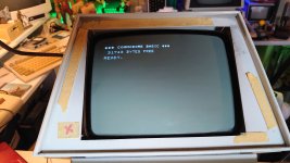
After replacing G4 We finally have the command prompt! Yay!!
Yay!!
Never thought we'd get there but I did have a good feeling about G4 being the issue after Nivags tests.
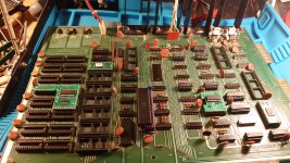
First thing I saw with the Tynemouth board in was just a few random characters dotted about the screen. After a few power cycles and fiddling with the Tynemouth board basic versions it was suddenly at the command prompt. I nearly passed out lol
My tests so far.
I have tested all the substitute rams as video ram I bought from eBay and they all work. Why didn't they work before, very strange.
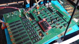
I now have in place the two new old stock 1981 6550 rams from little diodes as they also work.
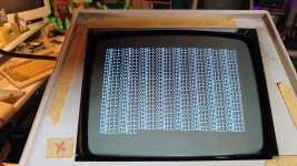
I did test a few pairs of the original 6550s but they sadly put junk on the screen but you can still make out in some instances the command prompt. I will test more of them in the future.
With the Tynemouth board removed using the CPU and using the system ram from Nivag and original roms I only get a screen of characters that we have been seeing. So some of, if not all of the roms could be bad or and bad sockets.
With pias and via back in.
The keyboard has some keys that do not work so as a work around I have plugged in my pets 3016 keyboard for tests.
I have run a basic programme i.e 10 print "hello" and it ran initially but the computer freezes sometimes since repeating the programme. Not sure why.
Also the tape motor runs constantly.
Not been able to run a programme from the datasette even though it plays on this pet and is confirmed working on another pet.
I have cleaned the datasette port as it was very dirty.
Just though I would let you all know how far I have gotten today.
Considering the state this Pet was in when I got it I never thought I would see it getting this far in terms of a command prompt.
I will enjoy it while it lasts just incase something else fails.
Yay!! Never thought we'd get there but I did have a good feeling about G4 being the issue after Nivags tests.
First thing I saw with the Tynemouth board in was just a few random characters dotted about the screen. After a few power cycles and fiddling with the Tynemouth board basic versions it was suddenly at the command prompt. I nearly passed out lol
My tests so far.
I have tested all the substitute rams as video ram I bought from eBay and they all work. Why didn't they work before, very strange.
I now have in place the two new old stock 1981 6550 rams from little diodes as they also work.
I did test a few pairs of the original 6550s but they sadly put junk on the screen but you can still make out in some instances the command prompt. I will test more of them in the future.
With the Tynemouth board removed using the CPU and using the system ram from Nivag and original roms I only get a screen of characters that we have been seeing. So some of, if not all of the roms could be bad or and bad sockets.
With pias and via back in.
The keyboard has some keys that do not work so as a work around I have plugged in my pets 3016 keyboard for tests.
I have run a basic programme i.e 10 print "hello" and it ran initially but the computer freezes sometimes since repeating the programme. Not sure why.
Also the tape motor runs constantly.
Not been able to run a programme from the datasette even though it plays on this pet and is confirmed working on another pet.
I have cleaned the datasette port as it was very dirty.
Just though I would let you all know how far I have gotten today.
Considering the state this Pet was in when I got it I never thought I would see it getting this far in terms of a command prompt.
I will enjoy it while it lasts just incase something else fails.
Attachments
daver2
10k Member
Party time! Well done!!!
The cassette motor constantly running is either the VIA or transistors Q1, Q2 and/or Q3 OR PIA#1 or transistors Q4, Q5 and/or Q6.
The VIA is Cassette motor #2 on J3.
The PIA is Cassette motor #1 on J6.
It is likely that your 'flakiness' could be due to 'flakey' ROM or RAM.
You really need to get my PETTESTER working... I think I have stated that on a number of occasions...
Dave
Last edited: