• Please review our updated Terms and Rules here

Commodore PET 2001-8 text wobbling on screen

greniu

Member
Joined
Dec 8, 2022
Messages
23
Hello Friends,

I am trying to fix my Commodore PET 2001-8 (chicklet keyboard) problem with wobbling text on the screen. I can see a little horizontal text movement when displaying it on PET CRT and on my LCD monitor connected via RgbToHDMI adapter too (with CRT wires disconnected from the board). So the problem is not related with CRT board for sure but somewhere on the PET mainboard or power supply. This PET mainboard is 320008 version.
I have 220V 50Hz rails in my home. PET has label 220V, current 0,6A. Someone told me that this problem can be caused by electricity frequency and first PETs were produced for 60Hz. Could it be a problem here?

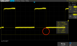
I have checked all 4 Voltage Regulators TL7805C (VR1, VR2, VR3, VR4) with my oscilloscope, and I see proper 5V DC with a small ripples.
I see also proper 9 VDC and 16AC voltage on J8 connector. Everything works perfect except this problem with wobbling text.
I also think this wobbling text can be a cause of those ripples and I can see them on all VR's. I have checked the schematics and noticed that VR3 is responsible for this IC's part where video and CPU is powered. I was thinking of swapping VR3 with a new 7805, but I don't suspect it might be faulty.

Where should I look for any evidence of such behavior? Can anyone point me to what I should check?
Thanks
 
First of all, what test equipment have you got?

What is the peak-to-peak measurement of the ripple?

Also, when you say ripple, what do you means? Do you know what frequency it is at?

I would resist the temptation to swap anything before we know what we are dealing with!

Dave
 
I can attach also VSYNC and VIDEO signals output from J7 as well if this helps. Is wobbling text effect visible on HSYNC as those small ripples at the end of each line? Or should I look at it somewhere else?
 
HSYNC signal is 60Hz.

SDS00002.png

VIDEO signal is 30Hz. I assume that these dots under the line are the text displayed on output.
SDS00003.png
 
Can you post a video of the "wobble" you are seeing on the screen, it might give a clue as to where the problem is originating.
 
Hi, I am using User Port and instruction according to Chuck Hutchins video
Also I am using the same profile.
 
Can you post a video of the "wobble" you are seeing on the screen, it might give a clue as to where the problem is originating.
hello, Here is recording from the captured picture.
 

Attachments

  • Commodore PET wobbling text.mp4
    1,001 KB
This is very strange. I used "Auto Calibrate Video Sampling" in RgbToHDMI device menu and I can see static picture now!
So sampling probably misled me and I thought that there is something wrong in the mainboard. ahhh. So does it mean the mainboard TTL video signals are working correctly?
I will try to focus on CRT board now and check all capacitors.
 
There was a phase shift error in the horizontal timing of the text signals with respect to the H drive pulse timing, but not the cursor which was interesting.

It might not mean much, unless you had the real CRT VDU connected and saw it there.

If it does in on the actual PET CRT VDU, can you post a photo of that. The fault is not indicative anything wrong in the VDU in this case (for example likely unrelated to any capacitor issues in the VDU). It can be with other types of VDU which have an H scan oscillator locked to the incoming H sync, but this is not the case for the PET VDU where it uses an H drive signal.
 
Hi. This is video from PET CRT (attached). The text shakes.I haven’t recaped it yet.
 

Attachments

  • pet_video.mov
    3.9 MB
Last edited:
Can you lift up the lid of the PET to move the VDU further away from the power transformer and see if that is the cause.

After that, if it wasn't, the next thing to do would be to check the power supply voltages for ripple with the scope.
 
Can you lift up the lid of the PET to move the VDU further away from the power transformer and see if that is the cause.

After that, if it wasn't, the next thing to do would be to check the power supply voltages for ripple with the scope.

hello, I recapped videoboard today. No difference. I have noticed that when I move VDU further away the PET I see only first line shaking but it was when I took the board out of the metal VDU case. I also applied some Deoxit onto Q9 potentiometer , because when I tried to touch it, the whole text on the screen was shaking. Also when I hit the videoboard with my finger when it was mounted inside the metal case, and the image also shook violently.
 
It sounds more like something is loose to me...

Either a potentiometer (as you have already found) or a loose wire in a connector or a connector pin that has a cracked solder joint.

When you say "videoboard" what are you meaning? The logic board within the lower half of the metal case or the monitor PCB within the upper half of the metal case (along with the CRT)?

Dave
 
hi Dave - videoboard in my case is monitor PCB. I will try to re-solder those joints and do a measurements. Any other ideas what I should look for?

I am pasting HSYNC signal from scope. When I zoom it I can see a strange peak line
 

Attachments

  • SDS00007.png
    SDS00007.png
    46 KB · Views: 6
hello. I think I have found a root cause. This is R20 (1 M ohm) on schematic. Does anyone know the replacement or the part name to find? thanks
When I touch it I see the text shaking on the screen. I suspect it is broken or not conducting electrity corectly. I have tried to clean it and deoxit, but no progress. I would like to eliminate this, as I see it suspicipus.
.Zrzut ekranu 2024-04-23 o 09.35.25.png
tempImagerr0V4u.jpg
 
Last edited:
Now you have it out on the bench, you can measure the resistance with a multimeter.

There should be approximately 1 MOhm between the two outer pins.

As you turn the potentiometer, the resistance from the centre pin to one of the outside pins should increase, while the resistance from the centre pin to the other outside pin should decrease. Both resistance readings should increase/decrease in a smooth, linear fashion.

This is a bog standard preset variable resistor with a value of 1 MOhm. Providing the physical data sheet measurements matches what you have, you should be good to go with any replacement.

R20 is the control for the vertical size - so a fault with this component should make the picture jump vertically (nothing to do with the horizontal scanning).

Dave
 
R20 is the control for the vertical size - so a fault with this component should make the picture jump vertically (nothing to do with the horizontal scanning).
Hi Dave, Thanks and very appreciate any advices.
So do you think that changing this R20 will not help with text wobbling? When I was touching this (with finger or plastic screwdriver )I noticed screen pulsing, and when changing potentiometer value the screen changed vertical size. But during that it the text was waving. It was also waving when I touched it with a little pressure or tap it with plastic screwdriver.

Is there any way to power PCB outside the PET power supply? I am wondering with a such test scenario when I connect external power supply to the E2 and E3 wires of the monitor PCB with 11V DC 0,5A power supply current and connect HSYNC, VIDEO and VSYNC to this PCB connector from PET mainboard only. I would like just to eliminate any problems with PET Power supply here (I know, PET mainboard is connected to it). I am looking for a best case scenario to test these component and eliminate any potential problem.
 
Back
Top