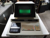
See attached a photo of the computer! :-(Sorry, but I strongly suspect an erroneous testing on that transformer. I wonder what the symptoms were when it was still installed in its circuit.
Frank
Upcoming Events:
| VCF West | Aug 01 - 02 2025, | CHM, Mountain View, CA |
| VCF Midwest | Sep 13 - 14 2025, | Schaumburg, IL |
| VCF Montreal | Jan 24 - 25, 2026, | RMC Saint Jean, Montreal, Canada |
| VCF SoCal | Feb 14 - 15, 2026, | Hotel Fera, Orange CA |
| VCF Southwest | May 29 - 31, 2026, | Westin Dallas Fort Worth Airport |
| VCF Southeast | June, 2026 | Atlanta, GA |
-
Please review our updated Terms and Rules here
You are using an out of date browser. It may not display this or other websites correctly.
You should upgrade or use an alternative browser.
You should upgrade or use an alternative browser.
Commodore PET 2001 flyback dead transformer.
- Thread starter Flavio
- Start date
daver2
10k Member
I don’t see a problem with your LOPT here - I see faults elsewhere within the monitor circuit. I will have a look this afternoon.
I see more of a problem on the vertical drive. The LOPT is in the horizontal drive.
Can you remind me if you have access to an oscilloscope or not?
Dave
I see more of a problem on the vertical drive. The LOPT is in the horizontal drive.
Can you remind me if you have access to an oscilloscope or not?
Dave
daver2
10k Member
Here is the schematic (I believe this was what monitor we deduced previously) http://www.zimmers.net/anonftp/pub/cbm/schematics/computers/pet/2001N/321445.gif.
We need to look (initially) at the vertical drive side of the circuitry. The first thing we need to do is to measure the regulated 12V supply on the monitor.
Next, does the vertical height control have much effect?
There are dc voltage measurements and expected oscilloscope traces on certain points as we transverse the vertical drive circuitry. These need to be inspected (from the input signal to the deflection coils) to identify where the faulty component(s) is/are. The oscilloscope traces are located in separate image files identified on the schematic by a circled number. http://www.zimmers.net/anonftp/pub/cbm/schematics/computers/pet/2001N/index.html.
Before we start, however, we just need to make sure that the schematic I have identified is the correct one to your actual monitor.
Dave
Hugo Holden
Veteran Member
I agree with Dave, the LOPT is fine, the problem is in the vertical deflection system.
The vertical deflection is both low in amplitude, distorted (hence the fold over and the bright area) but there is something else. It is offset downwards. This suggests that there is also (assuming the yoke is ok) possibly a moderate DC current via the vertical scan coils. Most likely capacitor C652 is failing. It could be due to other causes though and as Dave points out, check the power supply, then waveforms and the height potentiometer.
As you can see the vertical output amplifier has a similar architecture to a standard Audio output stage, complete with the Bootstrap capacitor C651. Also, it has both current and voltage feedback applied to the driver transistor Q603. These amplifiers are very easy to test & repair. It does normally require the scope.
Last edited:
Hugo Holden
Veteran Member
Also, notice that with these sorts of output stages, the DC voltage expected at the junction of the two emitter resistors, is usually 1/2 the supply rail voltage. So if the supply voltage is 12V, you'd expect to see 6V there, as shown on TP2. This is a quick place to check, with a simple meter, if the DC conditions of the output amplifier are "normal"
Hugo Holden
Veteran Member
Here is something that might help. I was playing around with the PET's vertical scan circuitry in the Spice simulator (still waiting to get my own PET) and found something interesting about it.
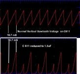
A good vertical scan relies on the voltage across the "Sawtooth capacitor" , C611 in the PET VDU, being a fairly linear ramp. So often, as it is in the PET VDU, the capacitor is charged by a current source.
There is an additional capacitor too which disables the current source when the sawtooth capacitor is being reset (discharged) C602, but these numbers might be schematic version specific. But in this particular vertical circuit, that feedback causes a very interesting effect when (and if) the sawtooth capacitor loses capacitance.
I have attached an image of what happens when the sawtooth capacitor drops in value from 10uF to around 1.5uF or below, it results in a very interesting effect of a twin amplitude scan, where there is an initial aborted scan and a secondary higher amplitude one. This result would pretty match what I see on the screen of your VDU, so this would be the first capacitor to check.
Attachments
daver2
10k Member
Hugo,
That is a very strange effect indeed!
Very enlightening, and shows the power that simulation can bring to faultfinding without any equipment at all.
I find (accurate) simulation packages invaluable before considering producing something in hardware.
Dave
That is a very strange effect indeed!
Very enlightening, and shows the power that simulation can bring to faultfinding without any equipment at all.
I find (accurate) simulation packages invaluable before considering producing something in hardware.
Dave
Wow!!! I have to be honest and I supposed I had not chances with my PET... I left the bone... 
Today I have decided to have a look anyway and... you are giving me new hopes (in the past I had the possibility to receive emails when new messages were sent to a 3D... I have to check if I can set this option again...).
At the moment I have two issues: the minor one is that the PET is not with me... the major (much much bigger) is that I am not a technician so I only follow some of what you explained me... but you were clear enough and I think I can do something.
And yes... I have an oscilloscope in my house so I can test the mobo better.
This weekend I hope I can meet with my friend asking him to weld the LOPT again and then I can start with some tests (also with his helps!)...
daver2
10k Member
Welcome back.
No problem, we can take it slowly!
Dave
No problem, we can take it slowly!
Dave
ScottishColin
Experienced Member
I know this is very old but I have a 3032 with the exact same symptoms; it turned out that the 7812 on the monotor PCB had failed (it was outputting 5V).
Hope this helps someone else.
Colin.
Hope this helps someone else.
Colin.
Last edited:


