• Please review our updated Terms and Rules here

Commodore PET 4008 with strange issues?

Apologies for being so silent here - first it was the chlorine gas incident, which provoked a H&S inspection, and now the communal workshop I used to rent a space in has been shut, for the near future!
I'm sourcing myself a scope, as I was borrowing mine from the shop. When I have one, and get a day free, I'll see to the PET diagnosis once more. Thanks for your continual patience and assistance all
 
Well, it sure has been a while...

I'm now fixing the PET out of a hotel room. It's a long story that's far from interesting, but that's the situation - only now am I finding time to work on it, on a bed with few of the comforts of my old workshop.

The good:
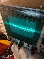
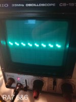
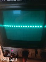
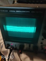
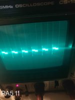
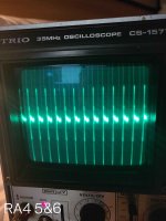
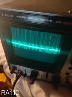
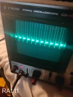
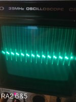
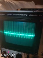
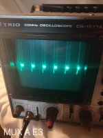
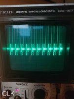
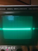
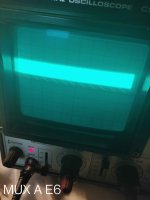
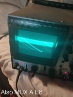
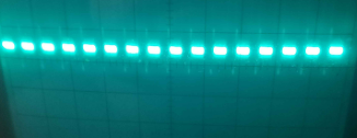
- I got myself a scope and performed the recommended tests on RAn, the clock signal and MUX A. I've attached images of my scope readouts from each (apologies for the shoddy pictures, poor calibration and manual operation - she's an old girl)
- Some of these seem about as expected if my maths is correct (dubious at best!)
- In some cases, where multiple pins should be on the same signal (RA1 running to pins 11 & 10 etc), some had an expected signal on one pin and noisy garbage on the other.
- Some seem alright at first glance!
- In terms of the others, I'm not entirely sure what conclusion to draw from the signal being fudged between the two pins - something faulty within that pin of the IC internally I presume?
- The clock seems a little messy but that might just be my scope operation as it was fine using the borrowed digital one way back when.
- One MUX A signal seems as I'd wager it should be, but the rest are either flatlining or doing... well... see attached.

Given that my scope is analogue and only has a limited number of sweep period settings, here are the assumptions I made for each measurement to their closest sweep period:
RA1 - Signal should be 1 division, sweep 2us
RA2 - Signal should be about 20% less than one division, sweep 5us
RA3 - Signal should be about 20% less than one division, sweep 10us
RA4 - Signal should be about 20% less than one division, sweep 20us
RA5 - Signal should be around 65% of one division, sweep 50us
RA6 - Signal should be around 65% of one division, sweep 0.1ms
RA7 - Signal should be around 28% more than one division, sweep 0.1ms.


The bad:
I have a confession, again. Working in a space like this isn't perhaps something I'm used to, especially having no solid table to rely on. When unclipping my earth clip to move it further down, I noticed just too late as it swung and shorted across CR5 and the positive pin (earth?) of C63 making some "lovely" sparks and a "nice" burning smell.
Yes, I am a buffoon.
Yes, I deserve full mortal humiliation for such a stupid error.
Yes, I feel just terrible about that. I can't undo my mistake, but as if I haven't made enough with this PET...
...and now the machine won't reach the memory test!
Have I killed my PET? Am I back to square one? It does seem probable, ever the optimist-
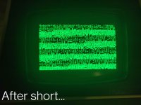
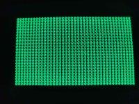
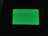
My hope is just that the EPROM got damaged in some way, or something easily replaceable (with any luck already socketted) in the video circuitry - is there anything I can rule out by that the PETTEST is at least displaying characters and nothing repeated / no patterns as before (see attached, final image).
I wouldn't blame you all for abandoning hope on this machine, and that is entirely my fault, time and time again.
But, I'm not going to.

All the best
 

Attachments

  • IMG_20240916_212131__01.jpg
    IMG_20240916_212131__01.jpg
    789.4 KB · Views: 4
  • IMG_20240916_224234__01.jpg
    IMG_20240916_224234__01.jpg
    600.8 KB · Views: 4
  • IMG_20240916_224044__01.jpg
    IMG_20240916_224044__01.jpg
    441.7 KB · Views: 4
  • IMG_20240916_213605__01.jpg
    IMG_20240916_213605__01.jpg
    450.9 KB · Views: 3
  • IMG_20240916_213723__01.jpg
    IMG_20240916_213723__01.jpg
    400.9 KB · Views: 3
  • IMG_20240916_213111__01__01.jpg
    IMG_20240916_213111__01__01.jpg
    597.2 KB · Views: 3
  • IMG_20240916_212511__01.jpg
    IMG_20240916_212511__01.jpg
    744.1 KB · Views: 3
  • IMG_20240916_212538__01.jpg
    IMG_20240916_212538__01.jpg
    521.9 KB · Views: 2
  • IMG_20240916_211742__01__01.jpg
    IMG_20240916_211742__01__01.jpg
    460.6 KB · Views: 3
  • IMG_20240916_211840__01.jpg
    IMG_20240916_211840__01.jpg
    569.7 KB · Views: 3
(Remaining images)
 

Attachments

  • IMG_20240916_224514__01.jpg
    IMG_20240916_224514__01.jpg
    492.9 KB · Views: 3
  • IMG_20240916_224934__01.jpg
    IMG_20240916_224934__01.jpg
    727.7 KB · Views: 6
  • IMG_20240916_225030__01.jpg
    IMG_20240916_225030__01.jpg
    762.1 KB · Views: 2
  • IMG_20240916_225127__01.jpg
    IMG_20240916_225127__01.jpg
    460.5 KB · Views: 2
  • IMG_20240916_225238__01.jpg
    IMG_20240916_225238__01.jpg
    483 KB · Views: 4
  • IMG_20240916_225336__01.jpg
    IMG_20240916_225336__01.jpg
    576 KB · Views: 5
  • IMG_20240916_232641__01.jpg
    IMG_20240916_232641__01.jpg
    630 KB · Views: 5
We are all dumb at some point in our lives. Don't worry about it!

I can see from the PETTESTER display that there is something not 100% correct with the video RAM sub-system.

Note that inverse capital 'O' and 'W' are missing!

Non-inverse capital 'O' and 'W' display correctly, so it is unlikely to be from the character generator onwards.

Are there any other characters that do not match what is in my PETTESTER documentation? Check the characters one at a time...

EDIT: The more I look, the more errors I am observing...

Dave
 
Last edited:
The none-inverse characters look all OK. The inverse characters not.

Some of the inverse characters appear to be always substituted for the same characters, others not.

My initial guess would be the video RAM at UF7 (this has the inverse data bit - SD7 - stored into it).

Failing that, it could be a short circuit between SD7 and some nearby track?

If both of your video RAMs are installed in IC sockets, we can remove them and do a bit of manipulation (if you can find 8 off 100 Ohm - or similar - resistors). We can pull the data lines from the RAMs high or low to simulate a single character written to the whole screen. If this test is successful, we can rule out anything past the video RAMs.

I am afraid your oscilloscope traces are not too helpful I am afraid. Perhaps we can return to this later when we have got the video sub-system fixed.

I don't think the video sub-system problem is the data buffers between the 6502 CPU and the video RAM though. So this rules out more circuitry to test.

I think we are down to the video RAM devices themselves (probably UF7) or the multiplexers UF3, UF5 and/or UF6.

Dave
I've left most of my resistors in storage, but I can see to getting 8x100 ohms. Both VRAM ICs are socketted.
I'll check SD7 after work for anywhere it could be shorting visually too.

May I ask, why aren't the scope readings of much use?
I only ask as if it's something to do with calibration etc I can redo it with different settings. If it's simply a problem with my setup then there admittedly isn't a lot I can do, but if the issue is my use of the scope then I'll gladly give it another try.
If the problem is me using it wrong I won't be offended at all, I can't say I've much practical experience with an analogue scope till now.

If it is of any difference, the tests I performed on the multiplexers were done before the short happened, and were at the PETTEST memory section.
Though I agree sorting out video first is the right approach.
I think perhaps I need to re-read the documentation too - it has been... almost half a year?
 
It is hard to tell at this point if additional problems have been introduced by a short.

One thing about scope recordings of digital circuits, what you should be on the lookout for are absent signals, stuck low or high when they should not be. Or anomalous logic levels between TTL logic high and logic low voltages, indicating usually that two outputs are "fighting" on the same line.

One of you scope recordings shows a sawtooth like wave which is clearly abnormal.
 
Key information to provide (with the image) is:

The timebase setting [X].
The voltage setting [Y].
Where the 0V reference is.

This image looks a bit suspect (and is true of a number of images):

1726581331047.png

I would expect to see a 'top' and 'bottom' of the wave. Not a line and a gap. When looking at some of the images, I keep thinking that the wave is going off the screen?

You have mentioned the limited timebase options on your oscilloscope. However, there are too many cycles of the signal present to make any sensible judgement as to the frequency etc.

Dave
 
Alright, I'll measure it again with fewer cycles. In each case the Volts/Div was set to 5 and 0V is dead centre on the vertical - this time I'll lower that to make the waveform bigger.
My camera struggles a bit to focus onto the CRT but I'll give it another go.
(This time I'll add the timebase to the image too, would make things a bit easier than tracing it to each signal respectively).
Thanks for the advice, I'll get back to you with better images
 
When looking at some of the images, I keep thinking that the wave is going off the screen?
In some cases it does seem to with retrospect (though, would one expect anything greater than +5V in the multiplexer?). I'll see if I can capture the whole wave(s).
 
It is a 35 MHz oscilloscope - so should be quite capable of monitoring signals on a PET!

I have found a picture of the controls on the CS-1577A. I would check the state of the NORM/CHOP button. For single channel use, this should be set to NORM (button OUT). In CHOP mode, the oscilloscope switches between the two traces. This is good if your are using the oscilloscope in 2 channel mode and want to perform timing comparisons. However, you must also remember that the oscilloscope is spending 50% of its time displaying channel #1 and the other 50% of its time displaying channel #2. Some people get confused and think the chopping frequency is part of the signal...

There appear to be very large 'spikes' on the edges of the signals. This could indicate that your probe is not calibrated. In this case you get 'spikes' and 'ringing' when the signal changes state.

Most of the signals you are monitoring will be TTL in nature - so +5V. In this case, I would set the Y channel to 1 [V/div] and adjust the Y shift base (with the probe on 0V) to be on one of the major divisions below the centre line and we can then use as much of the screen as we can to 'see' the signal whilst being able to easily read the voltage levels.

Dave
 
As @daver2 points out, with the scope(or any test instrument) one major thing is to get the best out of it. This obviously involves correct time base settings for the frequency of the wave you are dealing with, and suitable amplitude setting to help see it easily it on the screen. Generally it is best to keep the scope on DC coupling for computer work, and know where the zero volt line is. And label the photo well in a photo editor for posting, to help others figure out what is going on with the recorded signal.
 
Back
Top