• Please review our updated Terms and Rules here

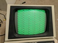
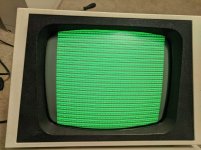
Commodore PET 4016 CRT Problems??

Yes I am using pettest2. Also the time to initialize the CRT is like very exact. It is the exact same period of time, every time. I'm inclined to believe this isn't an error, though I could be wrong.

I really don't think anything is wrong with the HSYNC or VSYNC output. Of course I can try to measure it with my Arduino anyway, as that's the only tool I have right now. Also, even if HSYNC and VSYNC weren't okay, I would still expect to see a picture on the display, even if its a garbled mess.
 
You say in post #7 that you are seeing data between UA2 and UA3 and that you see a clock on the shift register. Do you have the load signal as well? It is no good having the clock to shift the bits if it didn't load them in the first place.
3.45V steady on load. Doesn't change when the CRTC initalizes.

Datasheet for 74166 shows that its high unless it loads...this should be normal? I'm starting to wonder if the shift register is dead?...
 
Last edited:
3.45V steady on load. Doesn't change when the CRTC initalizes.

Datasheet for 74166 shows that its high unless it loads...this should be normal? I'm starting to wonder if the shift register is dead?...

3.45V is most likely a correct negative going pulse every 1 uS with the duty cycle of about 75%. A good /LOAD SR signal.

Even if the shift register was dead, wouldn't it be stuck at a 1 or 0? This should not cause a bad raster scan.

This is a very interesting problem!
 
I did check and even after it flashes and "dies", there is still an HYOKE and VYOKE present, so it's scanning alright, even if there is nothing displaying.

Wait ... Why wouldn't it being stuck at 0 cause a blank screen?
 
I did check and even after it flashes and "dies", there is still an HYOKE and VYOKE present, so it's scanning alright, even if there is nothing displaying.

Wait ... Why wouldn't it being stuck at 0 cause a blank screen?

Well yes or a bright screen as i'm not sure of polarity of video signal, but not craziness. Is your brightness turned too high?
 
The brightness was at its max, yes, but it didn't seem too high. Just about as bright as other tubes turned all the way up. It was just to see if I could see a raster from it being up but nope. Video signal is 0V black, 5V white(green). I turned it down to a reasonable level currently.

Also pin 11, UC2 is 0.2V, and never changes once it initializes. (output of the XOR of the shift register and UB2)

EDIT: 12 and 13 are also 0.1-0.2V. I'm thinking the problem resides before this point.

EDIT 2: Just to confirm again, checked the lines into the shift register, many of them have different voltages in the 0.3V-2V range, and they change a lot as the machine boots. I could see if I could set the Arduino up as a crude logic probe. It runs at 16Mhz, so I think I should get atleast an effect bandwidth of a few hundred Khz.

EDIT 3: Just checked pin 13 of the shift reg. not to be shorted to ground...just to make sure.
 
Last edited:
Also pin 11, UC2 is 0.2V, and never changes once it initializes. (output of the XOR of the shift register and UB2)

EDIT: 12 and 13 are also 0.1-0.2V. I'm thinking the problem resides before this point.

No, 0,0,0 on the XOR is OK. It is there to invert the video data if bit 7 of video RAM is set. On a power on screen LSD7 is not set.


After boot, Video RAM is cleared so the data in lines to the shift register will be mostly low even after the Commodore welcome screen. It may be hard to tell there is data using the voltmeter. A logic probe can tell. Make your Arduino into a pulse detector/pulse catcher where you can clear it and see if it catches a new pulse. Your Arduino is proving useful!
 
Arduino was polling a signal until the CRTC started, at which point it stopped finding any pulses. I know VSYNC was at 15 something KHz before the CRTC started when it dropped to 60Hz.

The inputs to the shift register are very active according to the 'duino

The output (13) to the shift register is dead as a doornail.

I'm probably going to do a lot component buy tonight since I also needs caps for my Mac Portable. Outside of the shift register, what else would be a good to buy, just because shipping right now is a hassle and I'd like to just order once and get some extra ICs.
 
Last edited:
Arduino was polling a signal until the CRTC started, at which point it stopped finding any pulses. I know VSYNC was at 15 something KHz before the CRTC started when it dropped to 60Hz.

The inputs to the shift register are very active according to the 'duino

The output (13) to the shift register is dead as a doornail.

I'm probably going to do a lot component buy tonight since I also needs caps for my Mac Portable. Outside of the shift register, what else would be a good to buy, just because shipping right now is a hassle and I'd like to just order once and get some extra ICs.

Your experiment with the arduino says the video monitor is working.
The shift register is not shifting any thing.

Places to check next.
Is the shift register getting clock?
Is the data changing on the load input?
Is there any changes on the data inputs?
You've said you don't have a scope but do have a logic analyzer. Use it.
Dwight
 
Pin 7(Clock) is dead on shift reg.
Starts at 1.7V, then falls to 0 once the CRTC init.

Pin 15(serial load) shows pulsing both before and after CRTC init.

I checked the data inputs before and they showed pulsing as well.

Since clock doesn't seem to be working, I will investigate there.
 
Well I tried the Char ROM chip...it showed a mostly same pattern though a few definitions were different. I put in the original and some lines were missing. Did it again and it was kinda flickery.

BASIC 4 ROM will not boot.

1) I think the VRAM is bad

2) I think the Char ROM socket is bad.
 
Based on that pattern, I can see that the high part of the address is not working. The characters are all the B0-BF chars. Would that be the even RAM chip complete failure? I have new 2114's here.
 
Good going on the shift clock...

That would be UC5 (upper nibble).

However, before unsoldering the VRAM; I would check to see what you are getting both sides of the latch UB3.

Also, if the CHARROM socket is BAD (post #36 point 2) shouldn't you perform a resistance check from the address pins of the CHARROM IC to the buffer Q outputs of the UB3 latch first?

The other thing I would check would be the address lines fed to the VIDEO RAM. If the same few memory locations are being addressed within the VIDEO RAM - and they all contain graphics characters (possibly stored there by the PETTEST ROM) then you could be being misled into thinking this is a VIDEO RAM data problem when it could be an address problem...

Dave
 
You might also adjust the vertical. No sense over driving the amplitude. Get the top and bottom lines back on the screen.
I think as one of the Daves mentioned, the address isn't count isn't working right. I'd not touch the VRAM yet. I see nothing on the screen that screams bad RAMs yet.
There could be bad VRAM but a lot of other things are more likely.
During the init, the processor is suppose to clear the screen. That means writes should happen as a burst. I think you mentioned that you have a frequency counter. Does it have a total count mode or is it just frequency only. If it does counts, it would be good to put it on the RD/WR pin of a VRAM and see how many counts one gets after reset.
Dwight
 
Last edited:
I can definitely do a resistance check. The results are sporadic when I seat and reseat the ROM chip. For the V-height of the image, I didnt show a picture of that but I did readjust it. I think the monitor caps need to be replaced, but since it shows a valid picture I won't worry about that until the mainboard is good to go.

Also of note, when the PET is flicked on within a second of it being turned off, it will start right up to where it was. If it is cold booted(ie...5s or more), it will do a full boot(wait 6s, etc). When the PET is booted about 2-3s after being shut down, the monitor comes up but it is in an invalid SYNC state where it is really high pitched and the picture is only on the right. I haven't made any measurements in this state, as to not damage my monitor.

I don't have time right now to go poking around in address signals, likely in a day or two.
 
Back
Top