Yes. The data is fetched in the second to the last cycle (16638), run through the ROM, and latched in the shift register. The video data for that last character goes out to the display during the last cycle (this is a simplification, it actually starts going out a few pixel clocks earlier than that) and VIDEO ON falls on the next cycle.
ah yes of course, there is some delay between fetching the data from the screen memory and seeing it on the screen... that would affect how to emulate this, if it were cycle-exact, which it isn't.
I've been pondering "when exactly" the emulation renders the scan line, relative to the position of the imaginary video beam. But there isn't really an answer to that, unless it can be related to something visible to a program.
Where the hardware accesses the video memory one-by-one, in successive cycles, the emulation in essence just halts time, then accesses all 40 screen locations at once. That has an effect on whether the hi-res program appears correctly or not, depending on how exactly it would do its memory accesses.
What the hi-res program does in its IRQ routine is that its writes to the 10 screen locations in the first text line, to prepare the first scan line. Then it waits a "long time", essentially the whole vertical blank interval. Then, just after the first of the memory locations has been read out to be displayed, the program starts to replace those values with those for the next scan line. It takes 60 cycles to store to 10 memory locations (see the readme.txt at that vice testbench location, which has a trace including clock cycles), so it has only 4 cycles to spare (2 NOPs). At first, the memory replacement would be only just behind the "beam", and as the line goes on it gets more and more behind. Only because it just tries to work on a small part of the screen, it's done with its replacements before the "beam" gets back to the first of them. And then it already has to replace the values again, for the next scan line.
For the emulation to show this correctly, with its instantaneous fetching of the screen memory, it has to do the rendering inside that 4 cycle window where the program is "between lines" as well. But (I hope I'm reasoning correctly here) this would need to be 1 scan line *earlier*, because the program on hardware stores the characters (slightly) ahead of time of being displayed, "behind the beam"; the emulation would then at the end of the line render the line in its already changed form, so the program appears to be "too early". This might explain why making the interrupt *later* rather than *earlier* makes the overall outcome better.
And unfortunately, different racing-the-beam programs would have different memory access patterns, so the instantaneous rendering would likely need to be at a slightly different time... bad news for emulation.
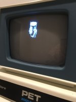
View attachment 1254923
It does produce a lot of weird "snow". The vertical garbage flickers around the left and right side of the "hires" box but the hires pixels remain surprisingly stable.
This is an amazing picture! I have never seen the "snow" so structured! You can even recognize half * characters in there. No doubt the locations of the garbage correspond to the access pattern to the screen memory; the first 3 stores of each line happen closer together than the other ones, and those might be the 3 garbage patches on the right. (They are coded as LDX #, LDY #, LDA #, STX, STY, STA) and then a sequence of LDA, STAs; I'm not sure why they did it that way since in the end it isn't faster). There would be 3 character spaces between them, right? That would correspond to fetching 3 the instruction bytes of the STA $8xxxx instruction.
This display partly seems to contradict my ideas about the timing earlier: I was expecting the replacement of the leftmost character to start right after it is displayed. But: the code first does LDX #, LDY #, LDA #, which takes 6 cycles and the STA $8xxxx which takes another 3, so that would account for 9 positions on the screen. And there is the fuzziness of the 2 cycle display delay, so all in all it isn't too unlike expectations.
I have been trying some "race the beam" experiments on this PET but the "snow" makes it difficult. The only way I've been able to do anything is to turn the screen blanking on (that takes 6 cycles), write some screen data, and then turn the screen blanking back off and make sure it is off when the beam is displaying the data. It's difficult and also means you can't have any static PETSCII graphics on the left or right side of the "hires" stuff.
Does that Bright Shining Star demo suffer the same problem? If so, I wonder how the maker created it, maybe they just tried emulation or a snow-free model...
I simulated both the static and dynamic board video circuits and they are effectively the same timing-wise though a bit different internally. The dynamic RAM can be read or written twice in one microsecond cycle (thus no "snow").
I found
https://github.com/skibo/PetVideoSim from a linked thread; I like that it can model the "snow". I wanted possibly to have the snow in VICE too, but I didn't know how to model it in a realistic way.
I looked at it with gtkwave but I'll need to find my way around it. For now it's just too many trees to see the forest, for this software person
")