• Please review our updated Terms and Rules here

Cromemco dazzler replica project

Ok,

Colour mode - where have you gone to?

The interesting thing is that most of the documentation I have seen on the Dazzler ports (in particular port 0Fh) state that D4 is only used when in resolution x4 mode (D6=1). This is NOT true. It is used in ALL modes to differentiate between colour mode and grey scale mode. The KSCOPE program sets the 0Fh register to a value of 30h (0011 0000) which is: D7=0 (unused), D6=0 (normal resolution), D5=1 (picture in 2K RAM) and D4=1 (colour mode). D3 through D0 are not used and are set to 0000.

First of all run my little test program and set D5=1 and D4=1 with all the others =0. This is the same mode as KSCOPE uses.
; Static level checks - Monochrome DAC disabled and colour DAC enabled.

Check IC7/1 for HIGH (D4) and IC7/2 for LOW (/D4).

Check IC15 pins 13, 1, 4 and 10 for LOW (Monochrome DAC disabled).

Check IC17 pins 11, 3 and 2 for Pulsing HIGH. (Colour DAC enable).

Check IC25 pin 10 for pulsing HIGH.

Check IC25 pin 9 for either HIGH or pulsing HIGH (enable high brightness colour DAC).

Check IC16 pins 11, 3 and 2 for pulsing HIGH (enable high brightness colour DAC).

; Check for 3.58 MHz.

Check the following IC pins for a 3.58 MHz signal. We also need to make sure this signal is a TTL signal - so that the logic '0' is < 0.8 Volts and the logic '1' is > 2.0 Volts (preferably higher).

IC14 pin 10.
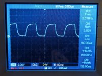
IC17 pins 1, 4 and 10.
IC16 pins 1, 5 and 9.

Check for pulses on the following pins. A logic HIGH should enable the colour gate, a logic LOW should disable the colour gate.

IC16 pins 13, 4 and 10.
IC17 pins 3, 5 and 9.

Check for pulses on IC14 pin 9.

Assuming the above is good, lets check the output of the gates. These should be bursts of 3.58 MHz when all of the inputs to the associated NAND gates are at a logic '1'.

IC14 pin 8.
IC17 pins 8, 6 and 12.
IC16 pins 8, 6 and 12.

Check the following gates for simple pulses.

Check IC14 pin 6.
Check IC25 pin 3.

Anything that looks strange, report back.

That should keep you busy and out of trouble...

Dave
 
Last edited:
just to catch up with the amendments to the PCB that we have identified.

IC 43 pins 10,13 & 14 - connect to adjacent rail
IC 39 pin 14 - connect to adjacent rail
Correct
IC 23 pin 10 - connect to adjacent rail
I don't have any modifications on this IC? should I?

IC 33 pin 10 - connect to adjacent rail
Correct
Cosmetics
R11 should read 30K
Two R23's !
IC 44 should be a 7474
IC52 should be a 7403
I think that's all
 
Wow I really have no idea how I missed that one.. Just added it to my board! Thanks for posting this recap. Boards still working same as before (works great in monochrome, but didn't resolve the color issue)
 
It wouldn't...

Don't forget, a not connected pin on a TTL chip generally floats high. It is just not good practice to leave any input floating. They should always be pulled high (preferably by pull-up resistors) to avoid electromagnetic interference (EMI) from causing a malfunction.

Dave
 
First of all run my little test program and set D5=1 and D4=1 with all the others =0. This is the same mode as KSCOPE uses.
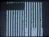
Ok FYI here's what my screen looks like in that mode:
PXL_20240403_172212498.MP.jpg

; Static level checks - Monochrome DAC disabled and colour DAC enabled.

Check IC7/1 for HIGH (D4) and IC7/2 for LOW (/D4).
Correct

Check IC15 pins 13, 1, 4 and 10 for LOW (Monochrome DAC disabled).
Correct

Check IC17 pins 11, 3 and 2 for Pulsing HIGH. (Colour DAC enable).
Pulsing high, correct

Check IC25 pin 10 for pulsing HIGH.
Pulsing high, correct

Check IC25 pin 9 for either HIGH or pulsing HIGH (enable high brightness colour DAC).
Yep, pulsing high

Check IC16 pins 11, 3 and 2 for pulsing HIGH (enable high brightness colour DAC).
Pulsing high, correct

; Check for 3.58 MHz.

Check the following IC pins for a 3.58 MHz signal. We also need to make sure this signal is a TTL signal - so that the logic '0' is < 0.8 Volts and the logic '1' is > 2.0 Volts (preferably higher).

IC14 pin 10.
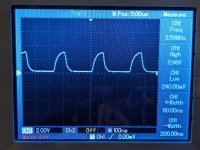
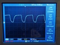
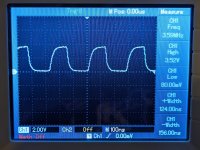
I am measuring the right frequency, but the waveforms look different for these so I'm going to post pictures. High/Low voltages is measured in the scope pictures.
IC14/10:
PXL_20240403_174513474.MP.jpg

IC17 pins 1, 4 and 10.
IC17/1 (voltage a little lower here but still in spec)
PXL_20240403_174624980.MP.jpg
IC17/4:
PXL_20240403_174706538.MP.jpg
IC17/10:
PXL_20240403_174800140.MP.jpg

IC16 pins 1, 5 and 9.
IC16/1: same as 17/1
IC16/5: same as 17/4
IC16/9: same as 17/10

Will get to the rest shortly..
 
Check for pulses on the following pins. A logic HIGH should enable the colour gate, a logic LOW should disable the colour gate.

IC16 pins 13, 4 and 10.
IC17 pins 3, 5 and 9.
These are all pulsing. They all look generally the same, except for IC17/3 which had a slower pulse. Let me know if you want any pictures.

Check for pulses on IC14 pin 9.
stable ~16khz clock here

Assuming the above is good, lets check the output of the gates. These should be bursts of 3.58 MHz when all of the inputs to the associated NAND gates are at a logic '1'.

IC14 pin 8.
IC17 pins 8, 6 and 12.
IC16 pins 8, 6 and 12.
Yes, I am seeing intermittent pulses @ 3.58MHz

Check the following gates for simple pulses.

Check IC14 pin 6.
yep ~16khz with a narrow +width

Check IC25 pin 3.
same, ~16khz but with a wider +width
 
I will take a more thorough look tomorrow.

However, I am not seeing anything jumping out at me.

Next is to fill the screen with a single primary colour and check the output from the DAC. I will post how to do this tomorrow.

The 'strange' 3.58 MHz clock is a result of the phase shift introduced by the inductor, capacitor and variable resistor (LCR) circuit to produce the red and green chroma signals (from the blue). They can be varied by adjusting the two potentiometers.

We are then into the analogue part of the mixer/video amplifier and potentiometer adjustments.

There perhaps is nothing wrong at all now, it just requires adjustment in a controlled manner.

Dave
 
Yep, there is a procedure for doing that!

I am on my phone, so it is not easy to do a copy and paste on a section of the Dazzler manual describing the procedure.

I have found one Dazzler manual to be better than another for this...

Dave
 
Correct

I don't have any modifications on this IC? should I?


Correct

I think that's all
Of that list, I am responsible for the missing link to IC23 pin 10 and IC33 pin 10. At least though the cards still work without them, but better for noise immunity to connect them. I will on my boards.
 
IC 43 pins 10,13 & 14 - connect to adjacent rail - fixed
IC 39 pin 14 - connect to adjacent rail - fixed
IC 23 pin 10 - connect to adjacent rail - fixed
IC 33 pin 10 - connect to adjacent rail - fixed

Cosmetics
R11 should read 30K - fixed
Two R23's ! - fixed
IC 44 should be a 7474 - fixed
IC52 should be a 7403 - fixed

PCB's uploaded to github
 
We are then into the analogue part of the mixer/video amplifier and potentiometer adjustments.

There perhaps is nothing wrong at all now, it just requires adjustment in a controlled manner.

Dave
Possibly so.

The only defect that was measured before, what that there appeared to be no color carrier signal on the active video, aside from the burst, on the output video signal, even though they were there on the outputs of the three gates of IC17 & 16.

But there is no issue with the other gate that supplies just the burst, mixing that signal into the virtual earth point, so it makes the idea of a defect in the mixing circuit and output amplifier improbable, or there would be no burst.

It is as though the connections from those color gate outputs via the resistors are not connected to the virtual earth mixing point, because if the burst is and it makes to the video output, so should the color signals. As noted it is not the usual suppressed carrier system of NTSC, and on a white signal there will (should) be R,G & B color carrier signals easy to see on the output video signal.

We need another recording of the output video signal. If the color carriers are there now, then the most likely thing would be the 3.58 MHz signal is a little too far off for the set to lock to and the color killer is on. But I think, probably, if the previous recording was correct , there are no color signals on the video.
 
Back
Top