• Please review our updated Terms and Rules here

Cromemco dazzler replica project

I just got mine back from JLCPCB and the silkscreen got removed from the copper. Strange, lol.

Well that's annoying! What did the preview show? Did you use the gerber github/zip that Angsar linked to and follow the readme?
 
Well that's annoying! What did the preview show? Did you use the gerber github/zip that Angsar linked to and follow the readme?
Yup used the provided gerbers and README and the silkscreen on the copper in the gerber viewer/preview image.
 
Well that's annoying! What did the preview show? Did you use the gerber github/zip that Angsar linked to and follow the readme?
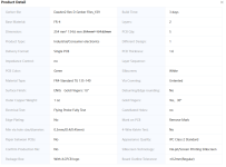
Here is the preview of my order and the order settings. Nothing in the copper was printed on the received board.
Screenshot 2024-10-23 203851.pngScreenshot 2024-10-23 203919.png
 
JCL say this about printing on copper

5. Special Character Design Instructions:​

To avoid interfering with component assembly, characters overlapping with solder pads or copper areas should prioritize exposed copper solder pads or copper areas (meaning the removal of characters from the copper surface). For customers with specific character requirements, you must ensure that the characters are printed on exposed copper solder pads or copper areas. Please make clear remarks when placing your order and confirm the production draft for the final result.
 
Here is the preview of my order and the order settings. Nothing in the copper was printed on the received board.

The only difference from my order was via coverings are "Untented" for Board #2. Mine were ordered as "Tented" for Board #1, as was specified in the README. Did you maybe swap these settings for Boards 1 & 2?

1729781019110.png
 
Last edited:
My experience with JLC ist that the preview is just a preview. They don't feel bound to it in terms of that the final product really looks the same. In fact preview and what the PCB workbench does obviously differ in some aspects. I guess they have included that somewhere in their general terms.

Technically, JLC is capable printing also on bare copper. But it is not finally controlled by the Gerbers. You have to tell them explicitely that you want the silk screen printing NOT being masked off by the openings of the solder mask. And you have to talk to one of their engineers, and to show them a picture of the original Dazzler so they understand what you mean. It is not necessarily sufficient to just talk with sales or support. That at least is my experience.

And JLC has not the option to gold plate the connector fingers only (as it is done by most S100 boards, including the Dazzler). If you chose that option, the whole board changes to ENIG.

If you like to be even more accurate, the vias for circuit board #1 are tented (=covered with solder mask), and untented for circuit board #2. JLC has an option to select for this in the self configuration (called via covering), but again you have to make sure with the JLC engineers that this option also is really being executed.

I have sum up all the hints in the README included with the Gerbers. I am planning to do another batch for those located in Europe, but I am still looking for a manufacturer who can gold plate the fingers only.

Hi,

Once you have a good setup at JLCPCB for the boards, maybe you can make the order "public" so other people can know they're getting everything correct? https://oshwlab.com/ ... Just an idea to make it easier for others.


.
 
Hi,

Once you have a good setup at JLCPCB for the boards, maybe you can make the order "public" so other people can know they're getting everything correct? https://oshwlab.com/ ... Just an idea to make it easier for others.


.
I would assume that the README included in the Gerbers is the natural place to put the hints there, but there is no reason not to also publish it at other places :)
 
I'm not sure why you're calling this a framebuffer based system? If you read the specs this is pretty clearly a vector based display engine. The "Functional Specifications" describe display rates in terms of the maximum number of line segments or characters it can stroke at 30FPS and the refresh buffer is 8K of 36 bit words containing coordinate data, not pixels. It appears to be a descendant of the Line Drawing System-1 from 1969. Also, Here's the a manual on Bitsavers that definitely makes it clear this is a vector system...
Very good findings, thanks! Yes, with a closer look the E&S Picture System indeed works out as a vector graphics system with refresh buffer for the line drawing commands, not for the pixels.

The Xerox Alto (1973) for sure had a frame buffer based graphics system, too. Maybe related to the work on the Superpaint system also done at Xerox Parc.

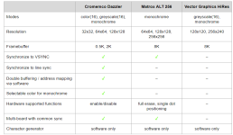
I agree that the Dazzler is not easy to program due to its 0.5K block oriented design and the weird pixel arrangement in each buffer location for monochrome mode. The Matrox on the other side did the pixel-to-bit-position conversion in hardware, which speeds things up significantly. However, the Matrox only supports a single graphics mode, and offering the same conversion for both nibble and 4x4 mode for the Dazzler probably would have required a third circuit board.

When I try to compare the three S100 boards I am aware of, it works out to something like this

1729843644183.png

Doesn't look bad for the Dazzler, overall.
 
Addendum to the above: following the reference to the IEEE publication on the Superpaint, there is also a history arcticle included in the same issue with some reference to frame buffers as essential part of a "painting system" (see for the article here). Citation: "In 1975, a full-color frame buffer for television resolution frames occupied three large racks of equipment, about three kitchen refrigerators in size, and cost over a million 1999 dollars. Today, this same device is called a graphics card and fits in one small slot in a personal computer. It costs on the order of ten dollars, and every PC has one."
 
Very good findings, thanks! Yes, with a closer look the E&S Picture System indeed works out as a vector graphics system with refresh buffer for the line drawing commands, not for the pixels.

The Xerox Alto (1973) for sure had a frame buffer based graphics system, too. Maybe related to the work on the Superpaint system also done at Xerox Parc.

I agree that the Dazzler is not easy to program due to its 0.5K block oriented design and the weird pixel arrangement in each buffer location for monochrome mode. The Matrox on the other side did the pixel-to-bit-position conversion in hardware, which speeds things up significantly. However, the Matrox only supports a single graphics mode, and offering the same conversion for both nibble and 4x4 mode for the Dazzler probably would have required a third circuit board.

When I try to compare the three S100 boards I am aware of, it works out to something like this

View attachment 1288514

Doesn't look bad for the Dazzler, overall.

Hi,

The DAZZLER is super easy to program with DZMBASIC created by Bob Ammerman ... I don't have any assembly language skills to even get started there, but with DZMBASIC I've written over 36 programs for the DAZZLER already.

This is the DZMBASIC disk ... http://www.brainless.org/Altair/Repository/DAZZLER-CPM-GRAPHICSZ80.dsk

As I get a new program working I keep updating this file on my website: http://www.brainless.org/Altair/Repository/WKP-DAZZLER-Collection.zip

Same thing for LWong's programs ... try his "BOMBER" game: http://www.brainless.org/Altair/Repository/LWong-DZMBASIC-Collection.zip

There is more programs and information on my webpage: http://www.brainless.org/Altair/Repository.html#section12

See my demos on YouTube: https://www.youtube.com/results?search_query=DZMBASIC


I'd love to work with a good assembly programmer to create some games for the DAZZLER ... individual games as well as two users on two different computers type games (DialUp, WiFi/Internet Connections) ...


.
 
Addendum to the above: following the reference to the IEEE publication on the Superpaint, there is also a history arcticle included in the same issue with some reference to frame buffers as essential part of a "painting system" (see for the article here). Citation: "In 1975, a full-color frame buffer for television resolution frames occupied three large racks of equipment, about three kitchen refrigerators in size, and cost over a million 1999 dollars. Today, this same device is called a graphics card and fits in one small slot in a personal computer. It costs on the order of ten dollars, and every PC has one."

Yeah, it's pretty nuts how much memory used to cost, and how quickly that changed over just a few years in the 1970's. When I read the Superpaint's specs that said they'd actually managed to stuff over 300Kb of memory into it in 1973 I was immediately wondering what the correct unit to measure the cost of that in: number of Cadillacs or number of houses, because that was still mainframe-levels of RAM at the time.

When I try to compare the three S100 boards I am aware of, it works out to something like this

It's not an S100 card, but I think when you're on the topic of prehistoric PC graphics I think it's worth remembering the SWTPC GT-6144, which worked with any computer that had a parallel I/O port available and at least got a fair bit of press coverage.

I also think it's a mistake to discount the contribution of some memory-mapped text-focused-but-also-did-graphics cards like the Polymorphic VTI, which also came out in the "late 1975-early 1976" timeframe. The VTI offered 128x48 mono graphics that could be freely mixed with 64x16 text; no color and worse vertical resolution than the graphics-only options, but a pretty good practical compromise for a display usable for both data analysis and video games.

I agree that the Dazzler is not easy to program due to its 0.5K block oriented design and the weird pixel arrangement in each buffer location for monochrome mode.

That is one of the funky things about the Dazzler. Especially in monochrome mode programming it has more in common with a "semigraphics" system than a modern framebuffer. Although, *shrug*, weird memory mapping was a feature that stuck around in personal computer graphics for a *long* time. (For instance, the highest resolution mode on the Commodore 64 has the pixels arranged like they're the contents of a character generator ROM, because from a logical standpoint the chip is kind of always in character mode.) Linear framebuffers without some kind of interlace or other gotchya were kind of the exception rather than the rule for a long time. (And of course there's the whole planar vs. packed pixel thing. I guess you'd lump the S-100 options that let you stack multiple cards together into an RGB stack into the planar bucket...)

I guess what makes the mono Dazzler particularly weird is it's the only system I can think of off the top of my head in which the "semigraphics" character it produced had more pixels horizontally than vertically. IE, the 128 pixel wide mono resolution of the Dazzler was essentially a 32x64 grid of 4x2 semigraphics characters; a typical "text and graphics at the same time" system would have 2x6 graphics grids (which with 64x16 would give you 128 x 48), and there were systems that could do a "full graphics" mode where they'd ditch the text and use the whole byte to do 2x4. (I believe the latter strategy, selected via attribute bytes, is how the Compucolor 8001 managed to pull off its maximum stated resolution of 160x192; an 80x48 grid of characters cut up into 2x4 graphics blocks.)
 
I guess what makes the mono Dazzler particularly weird is it's the only system I can think of off the top of my head in which the "semigraphics" character it produced had more pixels horizontally than vertically. IE, the 128 pixel wide mono resolution of the Dazzler was essentially a 32x64 grid of 4x2 semigraphics characters; a typical "text and graphics at the same time" system would have 2x6 graphics grids (which with 64x16 would give you 128 x 48), and there were systems that could do a "full graphics" mode where they'd ditch the text and use the whole byte to do 2x4. (I believe the latter strategy, selected via attribute bytes, is how the Compucolor 8001 managed to pull off its maximum stated resolution of 160x192; an 80x48 grid of characters cut up into 2x4 graphics blocks.)
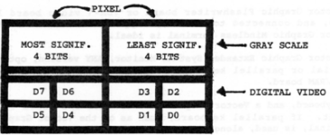
The Vector Graphics HiRes board uses a quite similar dot assigment in one byte (same scheme for greyscale, and also covering four bits horizontally and two bits vertically for monochrome, but with reverse order):

1729879854394.png
 
The Vector Graphics HiRes board uses a quite similar dot assigment in one byte (same scheme for greyscale, and also covering four bits horizontally and two bits vertically for monochrome, but with reverse order):

View attachment 1288559

I found the manual for this thing, and... wow. Reading it kind of makes my head hurt, the way they define "pixel" as being the area taken by the grayscale pixels even when they're in high-res mode... 🤪

I mean, I guess I get why they did it this way; it saves them having to change the rate they scan through memory between the high-res-mono and 16 gray modes; with this setup they can leave it fixed at a constant 64 bytes per line with the same address block repeated every other line... but, ugh.(*)

(* This seems like a decision that makes sense for the Dazzler, because it has a shift register line buffer on it that lets it play back a line of pixels multiple times for the scanlines they cover, but it's a little more baffling for this card since this thing straps directly onto a RAM card and turns it directly into framebuffer memory instead of using an across-the-bus DMA.)
 
Last edited:
I found the manual for this thing, and... wow. Reading it kind of makes my head hurt, the way they define "pixel" as being the area taken by the grayscale pixels even when they're in high-res mode... 🤪

I mean, I guess I get why they did it this way; it saves them having to change the rate they scan through memory between the high-res-mono and 16 gray modes; with this setup they can leave it fixed at a constant 64 bytes per line with the same address block repeated every other line... but, ugh.(*)

(* This seems like a decision that makes sense for the Dazzler, because it has a shift register line buffer on it that lets it play back a line of pixels multiple times for the scanlines they cover, but it's a little more baffling for this card since this thing straps directly onto a RAM card and turns it directly into framebuffer memory instead of using an across-the-bus DMA.)
Yes, as far as I understand, the Dazzler tries to fetch 16 or 32 bytes (depending whether 0.5K or 2K mode is enabled) in a single bulk transfer via DMA to the shift register memory which operates as a cache, so that maximum time remains for the CPU to gain access in between.

The Vector Graphic video buffer access is simply clocked by the horizontal counters, there is no buffering in between. Both greyscale and monochrome mode are using the same data path with the same clock, which requires to stuff the monochrome pixels in a similar way the Dazzler does. But due to the lack of a cache, it looks like the circuit for the monochrome mode has to grab every pixel byte twice (once for each line). But I need to have a closer look at the schematics.

The Vector Graphic doesn't use any I/O ports, so there is no vertical blank indicator for the program as with the Dazzler, but you can activate a "wait state" mode, so that the CPU is being kept off writing to the video buffer outside vertical blank in order to avoid "glitches".
 
I have posted this before. With regards to the table previoiusly posted, there is a really odd quirk about the Matrox ALT-256. In that any data you write into its onboard video RAM is not retrievable (except clocked out for composite video). So if you are creating an image file in it, you have to send a copy of the data elsewhere in memory, or it is not saveable to disk. They fixed this with the ALT512. The Dazzler doesn't have that issue because it hijacks computer RAM and the data for any image is there if you need to send it elsewhere to store or save your work.

As for the Dazzler's pixel organisation, I could see little sense in it and I had to bend my brain to create a single monochome graphics image (x4 resolution mode) of Che Guevara, starting out from a simple .bmp, it took multiple steps of processing, I had to write three custom 8080 programs. I selected his image for the task, because like the Dazzler he was revolutionary.

I explained how I managed it on pages 20 to 24 of my original Dazzlder article:


Attachments

  • che2.jpg
    che2.jpg
    183 KB · Views: 2
Last edited:
But due to the lack of a cache, it looks like the circuit for the monochrome mode has to grab every pixel byte twice (once for each line). But I need to have a closer look at the schematics.

Yeah, that’s what it does. It looks like they did it this way in order to reuse as much as possible between the two pixel output chains, including the demux that splits the input byte into two chunks.

In the grayscale mode it’s simple enough, for every memory read it spits out two pixels by sequentially routing the four bits from the top and bottom of a byte through a four bit DAC. But in high res mode instead of it doing the “easy” thing, which would be dropping the memory fetch clock in half and slamming the read byte into a shift register to clock out 8 mono pixels, it keeps using the “64 bytes a line split in half” mechanism and every other line clocks out the top and bottom two bits of each half. (In reversed order, no less.)

It saves a couple chips, but man, is it gross. It’s basically the same thing the dazzler does, but I’d say the memory ordering (because of the swapped bit order between lines) is even worse.
 
The new REV D boards work perfectly - this build set fired right up on the first attempt (after adjusting the pots/adj cap). Terrific work guys! I have 2 blank PCB sets left.
View attachment 1287692

Thanks to Hugo, Ansgar, Aron, Dave, Gary and anyone else I may have missed for tackling this project. I built up Rev C and. Rev D board sets after seeing Aron’s setup in action at VCF Midwest in September. Due to scrounging parts for 50 years, I only had to order a few oddball resistors, the 22uh inductors, 3 500ohm pots and 2 of the TMS3417. I am only had 1 of the 7483 adders but in meantime I am using a couple of 74LS83s to test the boards and they seem to work fine. I will order the proper 7483s this week. After setting up the boards per the manual, I ran the KSCOPE program and it looks fine. One interesting thing in the red color is not as accurate on the Rev D board as the Rev C board. The red is a little more orange than I would like. Probably has something to do with component tolerance but I will find out. I am just happy both sets are working.

I built an IMSAI in 1977 but I always wanted a Dazzer. Thank you all for making this a reality!

Here are a few pics of the builds and the KSCOPE display. The missing chip on the Rev D board is the 7483.
 

Attachments

  • IMG_9481.jpeg
    IMG_9481.jpeg
    3 MB · Views: 25
  • IMG_9483.jpeg
    IMG_9483.jpeg
    3 MB · Views: 26
  • IMG_9477.jpeg
    IMG_9477.jpeg
    2.9 MB · Views: 23
  • IMG_9476.jpeg
    IMG_9476.jpeg
    2.1 MB · Views: 24
Thanks to Hugo, Ansgar, Aron, Dave, Gary and anyone else I may have missed for tackling this project. I built up Rev C and. Rev D board sets after seeing Aron’s setup in action at VCF Midwest in September. Due to scrounging parts for 50 years, I only had to order a few oddball resistors, the 22uh inductors, 3 500ohm pots and 2 of the TMS3417. I am only had 1 of the 7483 adders but in meantime I am using a couple of 74LS83s to test the boards and they seem to work fine. I will order the proper 7483s this week. After setting up the boards per the manual, I ran the KSCOPE program and it looks fine. One interesting thing in the red color is not as accurate on the Rev D board as the Rev C board. The red is a little more orange than I would like. Probably has something to do with component tolerance but I will find out. I am just happy both sets are working.

I built an IMSAI in 1977 but I always wanted a Dazzer. Thank you all for making this a reality!

Here are a few pics of the builds and the KSCOPE display. The missing chip on the Rev D board is the 7483.

Hey glad they worked out, that's awesome! What CPU & RAM boards are you using with them?
 
Back
Top