It makes sense that the speaker is 100 OHms in the case where it is returned to -5v. Assuming the emitter follower "landed" the bias conditions in class A by a fluke of the transistor's hfe being close enough, then the max rms voltage swing would be (5 - 0.6) x 0.707 = 3.1v and the max power out prior to clipping 3.1^2/100 = 96 millwatts.
In the case of the 45 Ohm returned to gnd, the max rms voltage swing before clipping, assuming ideal bias would be roughly 4.4/2 x 0.707 = 1.55v and the power output 1.55^2/45 = 53 milliwatts,
The system with the 100R speaker and the return to -5V would have nearly twice the power output of the other with the 45 Ohm speaker returned to ground, assuming full drive was available in both cases.
On the other hand, the altered configuration to a grounded emitter amplifier I suggested, if a transformer is used (because the transformer stores magnetic energy in its core and the collector voltage swings higher than the +5V rail, the DCR of the primary is low, pinning the collector close to 5V), even running from the +5V and gnd, results in a max voltage prior to clipping of close to about (4.4 x 0.7)^2 (volts squared) / 45 ohms (or close) = 210 mW, in practice close to 200mW.
If you really wanted it to play something that cooked (like Marty McFly on his guitar), you could return the emitter circuit of the transistor circuit (with a transformer) to -5V (and the 10k resistor too, the 27k value would need altering to re-gain the 20mA collector current) then you could get about 960 milliwatts out (nearly a watt), but if you did that , I would replace the 2N3904 transistor with a BC639 instead or perhaps a 2N3053 with a heat flag on it. Class-A stages are not very efficient, their idle power consumption is fairly constant and a similar value to their max power output.
But..........
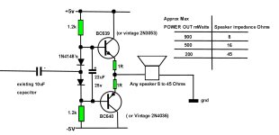
There is also a better option, with no transformer, and that is a "push-pull follower complimentary output stage".
In many ways if there is a -5V rail available this is the way to go, because it eliminates the requirement for an output transformer or output coupling capacitor, works with many impedance speakers, is a balanced system and much more efficient than a class-A amplifier, it is class B with a very low idle current, the power consumed from the supply is largely proportional to the volume (power) output, rather than the constant loss in class-A.
This class-B output stage has just enough initial bias to overcome cross over distortion, see attached.
I would go down this road if the -5V rail was readily available. It can also be made with period correct transistors, of the TO-5 cased variety.
For 16 Ohm and 45 ohm speakers, no heatsink would be required on transistors of these ratings, they might benefit from a small clip on one, in the case that 8 or 4 Ohm speakers were used and it was driven to full power. To find that out, simply run it to full power into a dummy load with a signal generator and measure the transistor's case temperature. In the case of the 45 Ohm speaker they would barely warm up at full output of around 200mW.


")

