• Please review our updated Terms and Rules here

CTX EzBook 800 No Power/No post

Well if it wasn’t dead before then it is now.
8C3AEFA3-7F5D-4628-985E-48CD874B9941.jpeg
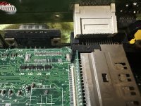
I let this area soak in vinegar for a bit and it did a bit too good a job of removing the corrosion. I did actually get more signs of life (more LED activity than normal, and the CPU heated up a bit) out of it before it broke off. This part was very likely the issue. I’d attempt to resolder it but as expected many pads went off with it.

RIP

Well, I guess I could attempt to repair it anyway. I’d have to desolder the VGA port for clearance and rig something up for the 6 broken pads. I can actually see where they go to but it’s all very, very small. A fun experiment I suppose. Maybe I’ll try.
 
I think I solved the mystery on documentation and why K6-2 isn't mentioned anywhere.
The answer? Needless confusion on CTX's part!

I have one of these: https://web.archive.org/web/20000303135451/http://www.ctxintl.com/fc3a300.html
Apparently, this is an EzBook F-Series, which as far as i can tell is just an 800 Series with an AMD chip in it. Nowhere on the laptop is F Series mentioned. The manual, laptop, driver CD, everything, call it an EzBook 800.

Mystery solved I guess...

This sort of nonsense is not uncommon. I once had to fix a dirt cheap HP laptop that had no actual model number. It seems HP was just buying whatever parts were cheapest and throwing them together, so components varied wildly between units within the same series. Trying to find drivers for that unit was a friggin nightmare.

Look on the bright side: just makes what you have even more rare.
 
Yeah it’s just as bad as the Macintosh Performa series…. Anyone have tips on soldering to vias?
 
Yeah it’s just as bad as the Macintosh Performa series…. Anyone have tips on soldering to vias?

If they're uncovered, just some flux and solder. If they have solder masking, use a rotary rubber polishing tip on a rotary tool to grind it off. If the VIA/trace is corroded, same process, use a rubber polishing tip.
 
A8DFE7D4-F66D-4EEB-918B-0E9743468136.jpeg
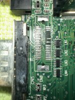
So six pads are bad. As you should be able to see in the photo, three of them go to traces coming out from the connector, and three go to vias under the connector. My question is how I should bodge to the empty pads from the ones underneath the connector, while allowing it to still fit flush on the board?

Also I haven't got any power tools for polishing unfortunately.

Also, does anyone know what type of component LN1, 2, 3, and 4 are? LN1 is damaged and will need replacing.
 
You'll need to invest in a rotary tool and supplies. Lots of solder braid and flux, as well as some low melt solder to avoid putting excessive stress on the already damaged PCB.

Even a cheap Walmart rotary tool would be fine, you can get them for $25-30, plus another 7-10 for the rubber polishing tip.

As for fixing those pads, you'll need to clean the entire area before you go messing with them. You'll need some thin magnet wire, probably 30 gauge. You basically clean the VIA up and put a small hook on the end of magnet wire and poke it into the VIA, then solder it in. Gently stretch the wire to the pad and center it there and cut it to length.

For the other pads that go to longer traces, you'll need to use the rotary tool to remove solder mask on the trace, then tin the trace. Get another length of magnet wire and solder it to the trace and bring it to where the pad is and cut it to length. Repeat for as many broken traces as you have.
 
Thanks for the advice. I’ll have to go out and get myself some of that magnet wire you’ve described from the sound of things.
A1A73D2D-8A83-457F-9EF6-8A3647A04046.jpeg
I cleaned the pads a bit so I can see the state of things a little better. I don’t think I’m going to need a rotary tool, I’m able to scrape back the solder mask just fine manually without damaging the copper.

I’m going to likely need to research the proper method for getting these soldered though. I suspect going pin by pin would probably not be ideal. And I’m going to need to remove the serial port behind it to get proper clearance.

I also really need to figure out what LN1 through 4 are. LN1 is damaged and I can’t figure out what type of part that is, and I need to replace it. Does anyone know?
 
L usually denotes inductors, maybe LN means inductor network, or a series of inductors in a single package.

You could try removing a good one and probing directly across the chip legs from one side to the other to see if there's continuity. You'd need an LCR meter to accurately get a value for what it is.

Though, I think if you tried to gently polish the legs and reflow with new solder, you may be able to salvage the existing chips.
 
The middle two pins on the side facing the battery of LN1 are broken, no continuity. I just probed with my meter and on intact pins, there is continuity across the package, whatever it is. I searched up inductor network but didn't get any good results.
 
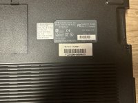
Also worth noting that the F series model number (FC3A300) is actually mentioned on the bottom as part of the serial number. I’d of course have no way of knowing this without the documentation though, and it also says 800 series….
02A64239-75D5-4717-B1E6-4B7BE96EF35A.jpeg
 
Back
Top