• Please review our updated Terms and Rules here

DC/DC converter modules

arlaneenalra

Member
Joined
Mar 26, 2024
Messages
46
I'm looking for a reliable source/brand/model of DC/DC Buck and Boost (or Buck/Boost) modules that are likely to have a consistent pinout/foot print and there are just way too many things to try. There are number of modules over on Amazon that I could use (like https://www.amazon.com/dp/B0CHY13H1R/ref=twister_B0CHXWYPM7?_encoding=UTF8&th=1 which is boost only so it can't pull a higher input voltage down and https://www.amazon.com/gp/product/B07NTXSJHB/ref=ppx_yo_dt_b_search_asin_title?ie=UTF8&psc=1 which will do buck/boost but has a nasty habit of shooting to its max output when the input drops below 3v). While the modules I've played with work, I don't trust them for more than experimentation and definitely wouldn't expect them to be generally available long term (i.e. I wouldn't want to design a PCB around them). Digikey has a bunch of modules, but they tend to be more expensive and it's a bit tricky to find the exact set of voltages/power outputs I'm looking for. I've seen https://www.pololu.com/category/136/voltage-regulators which looks promising, though I'd never heard of the company before they appeared in a Digikey search.

Basically I'm looking for:
* expected long term availability for a low volume purchasers (hobbyist level)
* If possible a standard or semi-stanard foot print/pinout in case that would not require a board redesign to replace
* preferably, modules instead of components. I'd prefer to have a prebuilt module over having to build around an IC
* variable and negative voltage output options available if possible.

Something like a pico ATX would almost be perfect except I need -22v for the particular project I'm playing with. That and the input voltage I'm working with can vary from about 6V to 12V since depending on it's source.

The end goal is to replace a kind of annoying PSU in a vintage laptop (Tandy 1400HD/FD series) that suffers from really nasty capacitor plague and is obnoxious to recap even if it hasn't blown up discontinued mosfet pack.
 
As far as a module goes, the PTH08080 series from TI is probably pretty reliable. They've been around about 15 years I believe. Buck only, 18V input max.

If you are throwing around the idea of a custom PCB, I might suggest "building your own" with the switching regulator chips that are available these days. You typically only have to add some resistors, capacitors and an inductor, all of which have suggested values in the datasheets. Here are some examples:

The Pololou options you posted look interesting. Let us know if you try them!

Looking around a bit, there are 7805 and 7812 drop-in replacements that use switchers. Could be worth a shot...
 
Those adjustable buck/boost modules in the second link have been around for a very long time in that form factor. I don't see them changing much. I've bought dozens of them over a decade from different sellers and manufacturers, and the footprints are pretty much identical.

As to their longevity, if you don't abuse them, they'll last for a very long time. I'd recommend putting a heatsink on the switching IC if you plan on drawing close to its rated current.
 
@Bentendo64 The PTH08080 looks promising for the 5v rail .. and that AZ34063UMTR-G1 ic looks promising for others. I was kind of hoping I could avoid laying out a bunch of voltage rails, but that may be the way I need to go :( Or designing a couple of reusable modules .. There's certainly enough room in the board foot print I'd be working with.

@GiGaBiTe Any thoughts on dealing with their nasty habit of going to 30v if the input drops too low?
 
Any thoughts on dealing with their nasty habit of going to 30v if the input drops too low?

Add an over voltage protection circuit, more specifically the one that disconnects the power rail when the voltage goes too high. Using a crowbar circuit would probably result in the buck/boost module blowing up since it shunts the output to ground, and those modules generally don't have any protection on them.

 
Unfortunately, I need around an amp on the 5v rail (could be a little more, I haven't fully measured it though so it could be a little more. What I'm replacing runs everything on a 2.25A 12V supply and the produces a 5, +/-12, and -22 rail off of that. The -22v rail has almost no draw, the 12V rail is for RS-232 right now but could power a HDD in some configurations. The 5v rail runs everything else, including potential floppy drives. The original supply can run off either an external 12v brick or a 4.8v NiCad pack rated at 4800mah. I've been toying with the idea of building a supply that can run off either a LiOn pack or the external brick. I've got a way to wire in the LiOn pack so that it doesn't get back fed if you connect the 12v supply and (in theory) doesn't create an extra drain that would interfere with in situ charging. But pulling the 12v supply causes enough of a dip in the output to reset the machine. Also, the prototype board is a hand soldered/wired nightmare :). Hence the reason I'm playing toying around with this idea at all.

Based on all that, the AZ34063 can't handle the current I'm likely to need directly. It probably can with an external mosfet/transistor, so that might be the way to go. The AOZ6605 linked above looks like it can only operate in buck mode. I'm wondering if I'm going to have to run a boost converter to push the "raw" input voltages up to something like 15V or and regulate down to 12V and 5V. The -22v rail will always have the least draw and I know it's under 100ma because a slightly modified version of https://www.amazon.com/dp/B0CHRTY125/ works just fine. Of course, that module is boost only and very very low current in all cases.

According to https://www.nomad.ee/micros/mc34063a/ boosting to 15V from 5V (absolute worst voltage on a 2s lion pack) at 2A load would pull about 14.5A and from 12V it would be about 5.2A. Realistically, protection circuits in the pack should trip well before hitting that point. The circuit will likely see somewhere around 6~8v on battery and about 12v on the brick. Of course, it's not likely to every see a 30W total load since the stock brick is only 26.4W and the floppy only model actually uses a power supply half that rating. But, If I can get this working, I'd like to have a workable board that others could use on the same machine.

Hmm, lot's to think about overall and I'm probably overthinking things. :)
 
That might actually be the answer I'm looking for. The whole thing overall draws about 27w (12v 2.2amp). So, using something like https://www.monolithicpower.com/en/mezd41502a-c.html to get a normalized 15v then building a couple of custom modules for the -22v and maybe -12v while using something like https://www.monolithicpower.com/en/mezd71201a-g.html and https://www.monolithicpower.com/en/mezd72401a-h.html for the positive rails might just do the trick ... at least for a better prototype than I have. The pinouts seem pretty standard too. Either way, I think that initial boots to 15v or so is probably going to be my best bet to get what I'm looking for. Time for a bit of experimentation ...
 
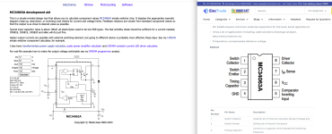
No wonder this hasn't been working the way I want it too!
Screenshot 2024-11-02 at 3.35.30 PM.png

I've been trying to figure out what I was doing wrong for about a week now only for it to hit me that the visual arrangement of the pins in the circuit diagram on the calculator don't match the pin ordering on standard chip. Sigh, I know better than this dang it!

Ah well, at least the ICs are cheap and I'm playing on a bread board ....
 
I was using something like this:

Which is a drop in 7805 type replacement, but it seems this one is discontinued. I think they have others like it if you look, maybe a VX series or something.
 
I think I'm going to do a mix of custom and pre-built. I saw those little modules but couldn't find them in all of the voltages I wanted. I've picked up a set of:

I'm doing a rough KiCad design that I'll probably post over on Github once I get it worked out. My plan is to take the input voltage and boost it from 12V/8V to 15V so I have a consistent baseline and then generate the other voltages off of that. The only one I couldn't find a drop in replacement for was the -22 volt rail.As an experiment, I'm playing with https://www.amazon.com/gp/product/B0C6GV9X4M which I should be able to drive off the 15V rail as well.
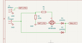
Screenshot 2024-11-02 at 6.05.55 PM.png
I need to re-look at this, I think I have the resistors setup wrong on there. (The 100k probably can't pull down the FET fast enough as wired .. hmm). In theory, I can wire a charging circuit in and actually have this thing able to switch/charge a battery in circuit. That is very very iffy and I was having issues with my prototype board drooping enough to reset the machine when I pulled the power brick. Also I'd want a real EE to take a look at this thing when I get the full circuit setup. I'm a Comp Sci with a little bit of electronics background so I don't really trust my designs just on face.
 
https://www.digikey.com/en/products/detail/mean-well-usa-inc/N7812-1PV/22119034 ... hmm I can use this to get -12V .. but unless I want to push my input to 24v (which is higher than most of the stuff I'm working with can handle, I'm not going to get the +12v most of the stuff I'm seeing want's 20~36v in to output +12 or doesn't produce enough power for the HD version. Hmm ... I might be better off just dropping a 7812 in there for that and and just leave everything else alone. I also discovered the pinout on that N7812 regulator is backwards from the TO-220 case of the LM7812. TO match them you have treat the big inductor as the "tab" side.
 
Back
Top