• Please review our updated Terms and Rules here

Decmate II question

Thought of something just now related to my Decmate II. I know the monitor gets its power from the host. I do know the monitor powered up and had a cursor. Doesn't this seem to imply that the +12v was working? Never could get the floppy to do anything that I remember. I also don't remember seeing the "Decmate II" message ever being displayed on the monitor. So that seems to imply that maybe the +5v was having problems? The faulty power supply is all in parts right now so I can't verify this.

If you get a cursor on the screen that means the +5 is there as well and at the least the data break part of the 6120 CPU is working. The display memory is just part of the regular memory and the display of characters to the screen is the refresh for the DRAMs. I remember reading somewhere that the CPU loses about 10% of the memory cycles due to the memory reads of the video hardware but loses nothing to refresh because that is automatic. We know that there are 115200 memory references per second due to the display (24 lines * 80 characters * 60 frames.) If each memory reference was 1.5 microseconds then the CPU would lose about 17% to the display. It would be about 12% if each data break is 1 microsecond. All the circuitry to generate the vertical and horizontal sync have to be present or you would not see the cursor (you would see a dot in the center of the display.) The fact that the screen is blank probably means that the CPU wakes up long enough to clear the display memory to blanks. A blank is a 040 code, not a zero so if memory is being read it is reading a 040 and that is being applied to the character generator ROM and you see blanks rather than whatever random code is in memory. With DRAMs, they tend to wake up either all ones or all zeros. It could be that a zero code also displays nothing but that would have been a waste of a character in the ROM. I don't know what the zero code is supposed to display but probably not the same as an ASCII space. Even if they are the same you still know that the 5 volts is enough there to run quite a lot of stuff and the 6120 CMOS CPU is more voltage tolerant than the TTL logic so the CPU is probably running.
 
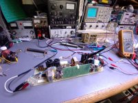
I put together the repairs and made new cables for ftcnet's two H7842 power supply units. I thought I'd share a couple of photos and a little mention of the specifics as I went along.

Both H7842 units were in a near-working state, and indeed as you've all noticed, they slowly pulse when operated with insufficient load; this is normal.

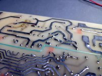
What I noticed on these units was mainly a case of poor solder joint condition, particularly on one unit and not too bad on the other. The worse of the two had been assembled with very short-cut leads, while both had had their leads cut after soldering rather than before. This practice of cutting afterward can result in failure as long-term reactions between the air and the mixed-metal interface can result in a loss of bond between the component lead and the solder over time, eventually creating a very good insulator made of oxide running between all the way through the joint. You may find components can be wiggled and you can see the leads thrust through the board, something I noticed on a few components in the worse of ftcnet's two units. So the initial task was simply to clear all the solder from any suspect joints and resolder with a high activity flux (I use AIM Glow-Core, it's quite a bit more effective than conventional rosin). It's important to ensure that while soldering, the wetting occurs over the entire pad and lead, but also up the lead and over its end, creating a completely sealed joint (yes, there is the other side of the joint which is obviously not sealed, but don't forget, the lead is factory tinned, and thus there is still no mixed metal interface exposed to the air). The other way to get around this is leave the lead cuts long enough that the mix-metal interface is well away from the solder joint, but you can't lengthen an already-cut lead.

After correcting all of the solder vagaries on both units, both became functional. I proceeded to check the capacitors and decided on replacement of a number of the small rubber-sealed aluminum electrolytics as they were well out of specification. The hermetically sealed capacitors were still exceeding specified performance, and being a bit more difficult to substitute nicely within the given space and ESR requirement, I left them in place. The input doubler/reservoir capacitors were also tested and visually inspected, perfect performance and no sign of trouble, so they were left in place.

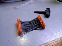
Next in line was correcting the cause of an overheat condition on the main power supply output connector pins. Fretting and oxidation had caused the original MTA-156 connector to melt; I polished all of the pins with paper soaked in metal polish to remove all oxides, then cleaned with acetone to eliminate any residue. I fabricated a replacement set of cables to ensure top performance.

Both power supplies were tested at full load for a few minutes, and at half load for over 24 hours each, and then shipped back for use in their computers.

Click image for larger version  Name:	IMG_20210805_192202738.jpg Views:	3 Size:	140.2 KB ID:	1222716 Click image for larger version  Name:	IMG_20210805_200055222.jpg Views:	3 Size:	141.6 KB ID:	1222717 Click image for larger version  Name:	IMG_20210806_162620276.jpg Views:	3 Size:	146.2 KB ID:	1222718
 
Last edited:
Back
Top