• Please review our updated Terms and Rules here

Diagnose issues: PET 4032 with PETTEST ROM

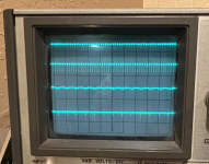
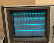
I suspect your problem is that as you move up the pins the frequency of the signal we are trying to measure is getting slower and slower.

As I think you are retaining the same oscilloscope timebase, I suspect that what you are observing is either all HIGHs (or all LOWs) as the complete cycle is "off the right hand end" of the oscilloscope trace.

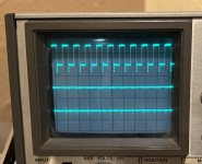
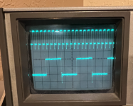
You will probably have to slow down the timebase a bit. Of course, this will have the undesirable effect of compressing your pin 1 reference trace.

As we move up the pins further, we may have to think again about how we are measuring things...

I hope this makes sense?

Dave
 
I thought I'd talk a little about de-soldering.
This is a skill, like working with wood or anything else.
The first thing I'd mention is you want a soldering tip with reasonable temperature control. You want one with what is called an Iron clad tip.
You are working with old electronics. This uses lead/tin solder. Don't mix solders. The newer solders use different metals and the mixing will cause higher temperatures to be needed.
Also use rosin core solder. Although, some like water soluble fluxes, these do need to be washed off. Some parts on these old machines don't like to be washed, like switches and relays. Rosin doesn't need to be cleaned. Never use plumber's flux on electronic equipment!
The next thing is, I see many online examples of poor soldering methods, on the web. The worst offender is not keeping a clean tinned tip. With the iron hot and sitting for some time at temperature, it will oxidize within minutes. Once the solder has oxidized all the way through a thin layer of solder, it will be hard to clean. If you expect to leave the iron on for more than a few minutes, add some solder to the tip, otherwise turn the iron off ( you may need to wait for it to reheat ). An oxidize tip requires one to apply heat for a longer time and use excess force to get heat to transfer. These both tend to damage the board and components.
Do not carry solder to the work with the iron. When working with old circuits always freshen the solder before attempting to do any solder removal. It just needs a little.
When first heating a connection, First make contact between the iron and the work. I then often give a quick tap of solder on the iron right at the joint between the iron and the work.
This gets fresh flux and a little solder between the work and the iron. It is a quick touch, not stuffing solder in.
I pull ICs of the board intact. I do not recommend this for a beginner. It takes a lot of practice and skill. I will describe doing this below but it doesn't make sense to damage the board to save a $1 part. I will describe the best method first.
Destroy the part, not the board method.
Use some close cutting diagonal cutters to cut the leads right at the chip edge. ( Many of the cheap, stamped out, diagonal cutters work fine. It hard to find better cutters that will fit between leads and close to the IC ).
Use a padded vice to hold the board. Use tweezers to pull the lead out once one has melted the solder from the solder side. You need to hold the tweezers off a little and then grab the lead once it is floating or the tweezers will heat sink too much heat. It is a timing thing. Before pulling the lead make sure it wasn't bent over on the solder side ( this should be checked before cutting the IC leads and be straightened ).
Clean the holes with either a good sucker or solder wick. I prefer suckers but that is up to you. I find solder wick to be too easy to get multiple undesired contact and then too easy to rip up traces. Use one of the long suckers, not one of those short ones you see in tool kits. The long plastic 'Pullits' ( sp? ) are the best.
Now I'll describe the 'save the part' method.
First freshen the solder on each lead. Heat the lead to melt the solder through the hole. Bend the lead with the iron, while it is hot such that it is floating in the hole ( in other words, not in tension to either side of the hole. You can feel the springiness with the solder melted and slight pressure to either side ). Suck the solder from the hole. Gently, pluck the lead, with a small screw driver or the iron. Not enough to bend the lead. It should make a slight plink sound and not a dull sound ( a skill that is learned ). Often times there is a small amount of solder on the IC side of the lead holding it to the eyelet. If it is really tiny you can beak it loose with needle nose pliers by squeezing across the sides from lead to lead with the tip of the pliers angled to favor the lead need addition work. This is not intend to beak the lead loose if there is a large blob of solder, this is only if the lead looks like it is sitting on the surface of the board with no noticeable meniscus of solder. You may have to refill the hole with solder and remove the solder again to get it truly clean.
Gently pry the IC from an end to see if there are any remaining leads not free.
Once you have the part removed, it is possible that the feed through is damaged.Make note of any leads that require solder connection on both sides of the board. When replacing the IC, remember to add little solder on the top of the board as well as the bottom ( I rarely damage them but it does happen. Work slowly ).
Always keep a clean tinned tip. Never press hard to make the solder melt. The traces on the board are held by an adhesive that softens at soldering temperature. Force will damage the board!
I hope this instruction is complete enough to help. Read this several times until you understand it all.
I will repeat, keep a clean tinned tip!!!!
Dwight
 
Hi Dwight.

A Happy New Year to you.

Just a query about whether you posted to the correct thread or not...

Dave
 
Probably Dwight's post should be posted at the top of every repair thread.

The thing is though, it does take many years to develop excellent de-soldering and soldering skills. They don't come out of thin air.

Part of it is that the components and pcb's are variable and each situation needs special consideration.

Phenolic pcb's are also much more fragile than fiberglass types and removing heat sensitive parts, such as Germanium transistors requires more special skills.

This is why, if you look on the Vintage radio and TV forum's, the TV sets with the lowest probability of successful repairs are early 1960's vintage Germanium transistor sets with compact construction and crowded phenolic pcb's.

The skill set to deal with these vintage TV's from both the theoretical and practical aspects, including soldering & de-soldering, is rarely possessed in many cases by the people attempting repairs, so the repairs create much more damage than problems they solve and a downhill spiral destroys the set.

And it is hard to explain all the details in a few sentences(though Dwight did well). As an extreme metaphor, it might be like trying to explain to somebody how to play the guitar like Slash did when he did a cover version of Jimi Hendrix's Hey Joe (have a look/listen its on youtube). Also the early CRT's in these set were not designed to be tested on CRT testers, and they get damaged very easily. People believe what they read on the internet about testing CRT's with testers, it does not occur to the repairer that by far the better & safer test for CRT performance, is to inspect it running in the set, TV or VDU that was built to support its function.
 
Last edited:
I made several mental notes to add to Dwights soldering guide but by the end all but one was covered and he didn't go into using a desoldering station so it was mute as well. Great advice...

I'll add a couple points from my days teaching college electronics lab practices....

Get some practice boards. Any through hole board of no value will do. I used the power supply boards from printers and copiers. They often have some high value caps to save. Just be sure they are discharged as they will be taken from an old machine that had been unused for a while.

If you use a desoldering station don't just jam the tip around in circles like you see in so many videos. Just gently rock it a little too get a good seal without sliding it on the board.

Finally, limit your time on part. If it's taking more than 5 seconds, maybe 10 on a heavy ground plane, then let it cool before trying again. Continually pouring more and more heat into it is a ticket to lifted traces. If necessary you may need a heavier iron tip or more heat.
 
Hi Dwight.

A Happy New Year to you.

Just a query about whether you posted to the correct thread or not...

Dave
Hi Dave
At some point, he may need to make a repair. I thought I'd add this before damage was done.

I don't think it was made clear as to how to do a piggy back RAM, as well.
Basically, one slides a new part over the broken on such that the spring tension of the leads makes electrical contact with the RAM that is suspected. In some cases it will make the board work correctly, in some case is will change the behavior of the board and lastly it may do nothing at all.
If it does make any change, it is likely that the part being piggy back is likely bad. One can then replace the failed part with reasonable confidence that you were doing the right thing.
Even TTL parts can sometimes be piggy back to get a working board, depending on the failure mode and the direction of the signal fail on the output, TTL is typically a hard pull down and a softer pull up. So, if it is a failing input lead that causes the output to be stuck high, piggy backing the part can make it work. Most failures for TTL that are mounted are failed bonding ( or an open ).
I do highly recommend getting an oscilloscope, like Hugo suggest. One does have to know what to expect to see. Dave can help with that. Then, if this is the only classic project you intend to do, a 'scope is a heavy investment for a one time use. One might borrow one instead.
Do note, there are many things that digital 'scope do better than an analog 'scope. On some special purposes only an analog 'scope will work. Most analog 'scopes rarely have the ability to hold a waveform ( expensive ), while most digital sampling 'scopes can hold a single even, for viewing. I have several 'scopes and none of them are digital. Like soldering, using a 'scope effectively is a learned skill.
Before using a sampling scope, one should understand sampling and aliasing. It can catch one into going the wrong way on a problem, when it is just not setting up the 'scope right for the expected signal.
Dwight
 
@Dwight Elvey I really appreciate your input on this thread. In fact, as a newbie, I was going to ask questions on soldering that you have now covered. I do predict some repair will be needed on my PET soon.

I should be able to take more oscilloscope readings this weekend.
 
Bend the lead with the iron, while it is hot such that it is floating in the hole
From personal experience, which is not a lot but maybe someone finds it useful, I stopped doing that. Especially with leads that are really bent and stuck to the solder side of the board (where more force is needed to get between the component lead and the board). It often leads to slipping and scratching or hitting other parts on the board.
I now use a pair of small robust tweezers and bend it straight carefully while heating the hole with the soldering iron.
It's probably less wear on the iron tip as well? I hope it makes sense what I'm trying to say
This is a good idea. I've just been doing it with the tip so long that I don't think about it. For me, one less hot thing on the bench is one less burn on the hand.
Of course, if the iron is falling, I quickly dance out of the way. No heroics to save anything but me.
Dwight
 
@daver2 , I'm not sure changing the timebase is helping. I adjusted the timebase from .5 microseconds/div (in the doc) for Pin 6 to 1, 2, and then 5 microseconds/div. I attached the pics. The top waveform for pin 1 is indeed more compressed, but the bottom waveform doesn't get any clearer.
 

Attachments

  • pin6_5microsecond.png
    pin6_5microsecond.png
    1.2 MB · Views: 5
  • pin6_2microsecond.png
    pin6_2microsecond.png
    1.2 MB · Views: 4
  • pin6_1microsecond.png
    pin6_1microsecond.png
    1.2 MB · Views: 5
In this situation you likely have to switch the scopes trigger signal source to the lower (other) channel, then likely the top waveform will be difficult to see, but you will be able to lock the lower waveform for inspection.
 
My PET lives! A local expert used his Tynemouth board to narrow down the issue to the first bank of DRAM. Unfortunately, all of the DRAM tests passed (not sure why). So we decided to replace each odd-numbered 4116 DRAM chip until we came to the faulty chip. I remember @daver2 mentioning that UA19 was a strong candidate for causing the issue, so he replaced that one first. JACKPOT!

Thanks for the assistance, all!!!! Now to clean the case, replace the badge, and get all of the keyboard keys working.
 

Attachments

  • pet.jpeg
    pet.jpeg
    192.1 KB · Views: 10
Well done...

So, more correctly, we used PETTESTER and a bit of grey 'wetware' to diagnose a faulty UA19 back in post #58 but it never got replaced :)...

Have you checked out the cassette port, user port and IEEE488 ports though?

If not, now you have BASIC up and running, you should be able to test these items out.

Dave
 
The cassette port works, not sure about the user port and IEEE488 port. I fixed the keyboard today after watching Chuck's video. Still need to verify all keys work.

How do I test the ports using BASIC?
 
For the IEEE488 port, there is a book (that has been referenced many times on VCFED) containing a BASIC test program.

I am just on my way out at the moment, but I will get you a link to it when I return.

For the USER port, you can POKE the direction port to make it an output, and then POKE values to it and measure the voltages on the edge connector. Again, I can post a procedure upon my return.

Dave
 
Back
Top