• Please review our updated Terms and Rules here

Diagnose issues: PET 4032 with PETTEST ROM

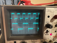
UE8 pin 2 and 4 - check.

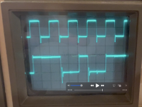
You have x10 magnification on the horizontal. What is the timebase time/div set to - and is the switch on CAL for the timebase? The x10 will (of course) add a factor of 10 into the timebase setting.

Dave
 
Pin 2 on UE8:
8 divisions.
Sec/div set to 2 microseconds (0.002 ms)

Pin 4 on UE8:
6.5 divisions.
Sec/div set to 5 microseconds (0.005 ms)

How does the x10 magnification factor in here?

Is the switch on CAL for the timebase?
Not sure. I don't think this oscilloscope has that?
 
If you have the x10 magnification ON, then this speeds the timebase up by a factor of 10 over what is shown on the timebase knob.

Therefore, I suspect your timebase to be 0.2 microseconds/division for your first example.

I suspect (from looking at your photograph) that the CAL position is the red knob fully clockwise (marked as fine). This (I assume) is the same red knob that you pull to switch on the x10 mode?

Dave
 
The sweep var knob needs to be turned and clicked into its CAL position.
The 10x magnification is the red one on the time base and it should be pushed in most cases.

Also it looks like the trace is out of focus? There should be a focus knob in the back, maybe try adjusting it..
 
I have worked out the discrepency...

>> Pin 2 on UE8:
>> 8 divisions.
>> Sec/div set to 2 microseconds (0.002 ms)

You state the horizontal timebase is 2 us/division.

However, with the x10 mode on, it is actually 1/10th of that so it is actually 0.2 us/division.

8 [divisions] * 0.2 [us/division] = 1.6 [us].

Converting 1.6 [us] into a frequency gives 0.625 [MHz]. This is not too dissimilar from theory based upon the schematics (0.5 [MHz]) and probably falls within the rough tolerances of our current measurement.

I would strongly advise NOT to use the x10 timebase mode under normal circumstances...

Dave
 
Ok, the sweep var knob is turned and clicked into its CAL position. x10 magnification is now OFF. Adjusted the focus knob. Red Position knob set to CAL. Do these look correct?

PIN 2
3.9 divisions
Sec/div = 0.5 microsecond = 0.0005 ms
3.9 * 0.0005 = 0.00195
512.8 Hz = pin 2 on UE8

pin2.jpg

***************************

PIN 4
7.8 divisions
Sec/div = 0.5 microsecond = 0.0005 ms
7.8 * 0.0005 = 0.0039
256.4 Hz = pin 4 on UE8

pin4.jpg
 
You are still out by a factor of 1,000.

You have milliseconds.

To convert from period to Hz requires seconds.

You can also convert from ms to kHz directly.

Dave
 
So it looks like:

512.8 kHz or .5128 MHz = pin 2 on UE8
256.4 kHz or .2564 MHz = pin 4 on UE8

Do these look right?
 
First off I would check the following pins in the order I have specified:

UE8 pins 2, 4, 6, 8, 17, 15 and 13. These pins should have square waves on them with each successive pin being half the frequency of the prior pin.

Next would be the two ICs in the order specified:

UE9 pins 2, 4, 6, 8, 17, 15 and 13.

Followed by:

UE10 pins 4, 6, 8, 17, 15, 13 and 2.

Ok @daver2 , I did 2 runs of measurements for the above procedure and both runs came out roughly the same. I will say that the waveform on UE9 was not a nice and straight square wave, unlike for UE8 and UE10. I included a short clip here of it: https://drive.google.com/file/d/1RuF8dzTCMbw0CQaOxjGT1eWFkYMIkpEd/view?usp=share_link


Here are the measurements:

UE8
Pin - Divisions, Timebase = Frequency

2 - 4, .5 us = 500 kHz

4 - 7.8, .5 us = 256.41 kHz

6 - 4, 2 us = 125 kHz

8 - 3.2, 5 us = 62.5 kHz

17 - 6.2, 5 us = 32.26 kHz

15 - 6.3, 10 us = 15.87 kHz

13 - 6.4, 20 us= 7.81 kHz

UE9
Pin - Divisions, Timebase = Frequency
2 - 7.9, .5 us = 253.16 kHz

4 - 4, 2 us = 125 kHz

6 - 3.2, 5 us = 62.5 kHz

8 - 6.4, 5 us = 31.25 kHz

17 - 6.4, 10 us = 15.63 kHz

15 - 6.4, 20 us = 7.81 kHz

13 - 5, 50 us = 4 kHz

UE10
Pin - Divisions, Timebase = Frequency

4 - 5, .1 ms = 2 kHz

6 - 5, .2 ms = 1 kHz

8 - 4, .5 ms = .5 kHz

17 - 4, 1 ms = .25 kHz

15 - 4, 2 ms = .125 kHz

13 - 3.2, 5 ms = .063 kHz

2 - 6.4, 5 = .031 kHz
 
They look fine. I'll take a look at the video after Church. I have to be there early today - I am on sound mixing duty.

Dave
 
The video does look a little jittery, but I have seen much worse on a working PET before now...

I would just file that on a 'yellow stickit note' in case we need to revisit it in the future...

Right, so we have demonstrated that what is going into UE8, 9 and 10 looks OK. Next, we need to check that what is coming out is also OK.

Let's concentrate on UE8 first. The process for UE9 and UE10 is identical to UE8.

When pin 1 is LOW, whatever appears on the input pins of UE8 (that you have already measured as correct) should appear on the output pins of UE8. When pin 1 is HIGH, any of the other two devices (UE9 or UE10) could be driving the output pins.

What we need to do is to trigger the oscilloscope on UE8 pin 1 and then examine one input pin (say pin 2) and then look at the corresponding output pin (pin 18 in the case of input pin 2) for the same signal - but only when pin 1 is LOW.

We then repeat for all 8 input/output pairs of pins on UE8, and then repeat the whole process for UE9 and UE10.

Now we just need to work out what setup we need for your particular oscilloscope and do some practice runs...

So it looks like you have a 2-channel oscilloscope (so you can measure both the input and output pins at the same time) and an external trigger for pin 1. However, I would suggest using channel 1 on pin 1 (as a trigger) and channel 2 to probe the input and output pins to start with. This way you will see the trigger channel.

I would set the oscilloscope to CHOP mode for this as you want both channels to be time aligned. This can introduce some odd visual effects as well as the oscilloscope switches between thectwo traces. Hence the reason to have a few practice attempts first...

Dave
 
Last edited:
Ok, I finally got chip clips for the UE8-UE10.

https://drive.google.com/file/d/1wBYlJVMHnPbEAiMzX9SDbX2MeJ4PjyxT/view?usp=share_link shows UE8 pin1 on channel 1.

https://drive.google.com/file/d/17TNSHb3KLfapw6Cw2tsoRmQGiYKEMWV2/view?usp=share_link shows UE8 pin2 on channel 1

https://drive.google.com/file/d/1jkZWRaezJCKpEsaWzOMhCOg3vCjVaQur/view?usp=share_link shows both channel in CHOP mode.

https://drive.google.com/file/d/1VDxduQNMrLmZDWenGb2_S8CzNTFSOpeA/view?usp=share_link shows a movie of the output pin (pin 18). It looks wonky.

I'm not exactly sure how to set the trigger level. Do I pull the knob out for triggering when the input goes low?
 
I'm not exactly sure how to set the trigger level. Do I pull the knob out for triggering when the input goes low?
Yup, on that scope pulling out the knob will trigger on falling edge of the waveform.
What I prefer to do in such a scenario where two channels are used is setting 2V/div (in the case of ttl signals, you should have 2-2.5 squares mostly) and position the signals in a way that makes them still readable, e.g. CH1 in the upper half and CH2 in the lower half of the screen.

The trick is to leave the source of the trigger (e.g. CH1) attached to the pin to trigger off while probing the rest of the circuit as explained in #93
 
Should it be pulsating like that? It makes it hard to compare to the other picture.
If I understood correctly the task is to compare the input / output pins, which should be in the same state while ue8 pin 1 is low (inputs=outputs), in the case of the video low, high, low, high.. when looking at the more visible waveform
When pin 1 is LOW, whatever appears on the input pins of UE8 (that you have already measured as correct) should appear on the output pins of UE8. When pin 1 is HIGH, any of the other two devices (UE9 or UE10) could be driving the output pins.
 
OK, I did some horizontal shifting and did another run.

pin1 is on top of the attached pics (timing)

pin 2 (input) clearly shows H, L, H, L, H

pin 18 (output) shows pulsating waveforms. I attached a screen grab from a video I made. The main waveforms don't seem as clear cut. I see a H, followed by the waveform going low while the timing waveform is also going low. Then going high while the waveform is going high. Shouldn't the signal waveform be at the desired state before the timing waveform goes low?

@daver2
 

Attachments

  • pin2_run2.png
    pin2_run2.png
    1.2 MB · Views: 2
  • pin18.png
    pin18.png
    2.4 MB · Views: 2
No, because pin 1 is the buffer enable signal only.

The actual contents of the bus will be sampled (used) later on by another control signal / system clock edge that you are not monitoring.

The second trace still shows the expected behaviour of H, L, H, L when the first trace is '0'.

Dave
 
Great! I did some more input/output pin pairs and put them into a doc for easier viewing. I don't know what to make of pin 6 and pin 8. They seem to show lines for HIGH and LOW together (maybe because I have the trigger set to falling edge). The output looks like all HIGH. Possible issue?


Datasheet ref for sn74ls244n: https://pdf1.alldatasheet.com/datasheet-pdf/view/837806/TI1/SN74LS244N.html
 
Last edited:
Back
Top