• Please review our updated Terms and Rules here

Digikit Reaction Tennis

falter

Veteran Member
Joined
Jan 22, 2011
Messages
6,580
Location
Vancouver, BC
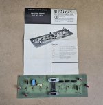
Couldn't resist this one for $20. I'm often perusing vintage electronics magazines and repeatedly see adds for these mail order electronics game projects. They don't seem to appear on ebay much at all - in fact looking on worthpoint this is the only digikit former kit that has ever showed up there.

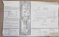
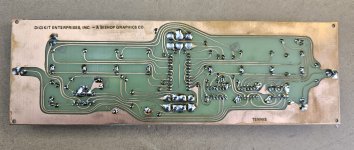
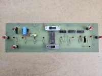
I actually plugged it in and it seems to mostly work! Just won't serve from the other player's side. I'm going to scan the documentation and create a new PCB from it so others can build their own for fun if they want. I've documented a couple minutes of it operating and it'll appear on one of my 'unboxing' videos.

Very cool little piece. Looks like it was built sometime in or after 1975.
 

Attachments

  • 20230826_095752.jpg
    20230826_095752.jpg
    2.2 MB · Views: 47
  • 20230826_095803.jpg
    20230826_095803.jpg
    2.2 MB · Views: 51
  • 20230826_095811.jpg
    20230826_095811.jpg
    1.8 MB · Views: 43
  • 20230826_095826.jpg
    20230826_095826.jpg
    1.9 MB · Views: 37
  • 20230826_101149.jpg
    20230826_101149.jpg
    4 MB · Views: 42
That looks to be a bit of light entertainment!

Should be simple to work out what is wrong with it.

Dave
 
It may simply be operator error. There is a slider switch that controls which player serves. But there is a reset sequence between serves and I think I'm possibly not getting it right. I can serve from one player's side and return the 'ball' from the other but I can't serve from the one side no matter what I do.
 
By the looks of it, you need to change the 'serve' switch from A to B to change who serves. I assume you are doing that?

S3 is the serve switch and S4 is the speed switch (to avoid that confusion).

It might ne worth checking the two halves of S3 to make sure they are both working.

Dave
 
Last edited:
Yes if I read right, you serve, each player tries to hit the ball back in time, and then once a point is scored the point light lights up, then you change the serve switch, both players hit reset and then the player you've switched to serves? But it doesn't seem to work that way so far. Could be a flaky switch.. I'll have to check that first.
 
They got all the LEDs on the right pointing into the wrong direction on the schematics!
 
I have modelled the control logic, and I can't get it to work properly either.

Although I am still 'playing'. Yes, there appears to be a few issues with the schematic as well. What I need to do is to check the physical PCB layout with the schematic to check for further errors.

Of course, I have used the schematic to enter the logic into the simulator. So I will have replicated any schematic fault myself...

Dave
 
Faulty schematics? Ya don't say. :)

I have tried literally every switch setting but sadly I cannot get player a to be first to serve. Only player b. Components seem ok..
 
Did you test the switches out? It is no good trying every switch combination if the switch(s) are faulty...

Also, you should be able to identify with a logic probe which gate is holding up the s/r flipflops (formed from the cross-coupled NAND gates).

Can I suggest posting a video of what you are doing to operate the game?

I will implement the shift register and LED indicators in my simulator next - as trying to simulate the two initial LEDs for each player is somewhat confusing.

Before I do that (however) I will print out the two sides of the PCB photographs and correct the schematics! If there are other errors in the schematics that I have not spotted - then my simulation will not work of course!

Dave
 
I have already found the first discrepancy between the PCB layout and the schematic (after only 15 minutes of checking). I wonder which one is correct?

There are also a few 'design errors' that may work - but are very bad practise:

U4/13 is floating. It requires a pull-up resistor.

L2-L9 are drawn the wrong way around on the schematic.

S1 is missing a pull-up resistor at the IC input.

S6 is missing a pull-up resistor at the IC input.

S2/S5 is missing a pull-up resistor at the IC input.

I note the presence of C1/C4 on the output of the IC gates. I suspect these act to delay the LOW to HIGH transition of the gate output sufficiently to register at the input of the S/R flip-flop (to be demonstrated).

I have found more inconsistencies between the PCB layout and the schematic!

Dave
 
Last edited:
Hi Dave,

I briefly fired it up in a video at this timestamp. Not quite exhaustive, but I did literally try every switch combo off camera later, and yes the switches themselves seem to test good. Strong possibility of operator error here though.
 
Excellent. Thanks.

I think I now have a digital simulation that works. However, I have derived that by experimentation and my grey matter based upon the inconsistencies I have identified between the schematic and the PCB layout.

I now need to check your video again to see if how you are poking the buttons gives the same LED indications as I get.

Then I can derive a more accurate schematic from the PCB layout and see where that takes us.

The logic is fairly straightforward from what I have seen from my simulation - it is just confusing with the inherent errors in the article!

Dave
 
I have redrawn the schematic - so I think I can make some predictions of what you should see on the various IC pins with your logic probe.

It is important to print out the picture you have of the component side of the PCB - and annotate everything! Lay it out as per your video.

Player A is on the left and player B is on the right.

Player A serve button (left) is S1 and player A reset button is S2.

Player B serve button (right) is S6 and player B reset button is S5.

The speed switch (S4) is by the power supply (left fast, middle power off, right slow).

The serve switch (S3) is at the top.

If you put your logic probe on U5 pin 5 then the logic probe should indicate 'open circuit' with no buttons pressed and LOW when either S2 or S5 is pressed. Both of these buttons are in parallel - so (in theory) you only need to press one (1) of these buttons.

See what happens when you try this, then we can move on to the serve buttons.

Dave
 
You might also want to check the soldering out. It doesn't look too brilliant! There may be short circuits from blobs of solder.

Dave
 
I have redrawn the schematic - so I think I can make some predictions of what you should see on the various IC pins with your logic probe.

It is important to print out the picture you have of the component side of the PCB - and annotate everything! Lay it out as per your video.

Player A is on the left and player B is on the right.

Player A serve button (left) is S1 and player A reset button is S2.

Player B serve button (right) is S6 and player B reset button is S5.

The speed switch (S4) is by the power supply (left fast, middle power off, right slow).

The serve switch (S3) is at the top.

If you put your logic probe on U5 pin 5 then the logic probe should indicate 'open circuit' with no buttons pressed and LOW when either S2 or S5 is pressed. Both of these buttons are in parallel - so (in theory) you only need to press one (1) of these buttons.

See what happens when you try this, then we can move on to the serve buttons.

Dave
Finally got time to set this up again. So u5 works as expected. Open until you hit reset. I did manage to get a serve out from the player A side, but only if I move the speed switch to middle and then back to either side. And even then not always reliable. I think we may have some soldering issues.. ive noticed when I inadvertently flex the board by putting pressure on the player a side, the lights act up.

The switches themselves seem to test ok. I'm not sure how to test S3 and S4 precisely.. but I can see resistance changing on the poles or pins on the dime side I move the switch to, usually to zero. If more detail is needed I can draw up how I'm testing.

It does seem like we are getting random results though.
 
Hmm.. yeah I think we've got some solder or dry solder joint issues. For one thing, I noticed the point/resdy indicator light for Player B csme on when I accidentally touched it. I flexed it gently and it went on and off. So need to fix the soloder there. I can get it to fire from both sides but it's really fidgety.. I really have to press the serve button on whichever side with authority. But I did manage to bat the 'ball' back and forth about 5 times at one point. It does not seem to reset as the manual suggested.. you have to switch the speed selector to off and back to reset the LEDs and then mash the serve button to get it to serve.
 
We didn't actually test out U5. U5 pin 5 was a convenient place to set the two reset buttons S2 and S5. Do these buttons both work OK then?

The next test would be U2 pin 11. This pin should be LOW. Pressing S1 (serve player A) should cause this U2 pin 11 to go HIGH. Releasing S1 should cause U2 pin 11 to go HIGH once again.

The next test would be U2 pin 3. This pin should be LOW. Pressing S6 (serve player B) should cause this U2 pin 3 to go HIGH. Releasing S6 should cause U2 pin 3 to go HIGH once again.

Alternately pressing S1 (serve player A) and S6 (serve player B) should cause the serve LEDs (L1 and L10) to alternately illuminate and extinguish (i.e. one of L1 and L10 should be illuminated and the other LED extinguished).

S4 is the speed - but it is a 3-way switch with the centre way OFF. If you put your oscilloscope on U4 pin 11 - there should be a lower frequency with S4 one way than the other. The centre position is OFF (the positive power supply is disconnected).

We will get to S3 later...

The reset buttons do not work as you think...

Changing S4 causes the power to be killed to the ICs - thus causing them to 'reset' to some undefined power-up condition.

You probably need to clean the flux off with IPA and reflow any dubious solder joints. If the buttons are 'hesitant' then you may have dirty contacts and need replacing. But my above tests will identify this...

Dave
 
From what I see the 74198 register will have to be replaced with some alternative solution for a possible modern recreation due to difficult availability.
 
You can still buy them - a number of electronics stores still stock them (just)...

I was going to have a look for a modern equivalent though myself. They will probably be cheaper!

Dave
 
Hmmm, not as simple as I thought with off-the-shelf TTL logic devices...

You could use two off 74178s - but these are also difficult to obtain.

The alternative would be a programmed 22V10 GAL.

Dave
 
Back
Top