Hello everyone,
After completing my third revision Turbo XT clone ATX mainboard I feel I would like to move on to an AT mainboard design.
The main reason is that the Turbo XT while a really great and reliable and extremely versatile PC,,
and though I really love it, it does still have its limitations in use regarding software that is compatible with the 8088 and V20 CPU.
Anyone who is interested can visit my web page about my XT mainboard design in my hobby page:
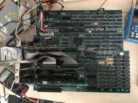
I am not sure what route I will go next but I have bought a NCR PC-8 MODEL 3279-0XXX mainboard which is a relatively close clone of the IBM 5170.
Unfortunately the mainboard arrived in stripped condition without a CPU, ROMs, CMOS clock and keyboard controller, and with only 256kb of DRAM.
However at least no leakage.
In my Ebay buy were also included two NCR Decision Mate V mainboards but without the video module. I am not sure what I will do with these.
This Decision Mate V is a strange Z80 computer because it can also be turned into an XT PC using some modules.
So a kind of CP/M / DOS hybrid it seems. I love the case design though.
The original PCB assembly quality of the NCR PC-8 AT mainboard which was done in Europe at the time is terrible.
The 4 layer PCB has been soldered onto the slot connectors in warped state because of the solder bath heat.
It's simply not straight anymore, but so be it, I am not going to desolder and straighten it using heat because I feel it's too risky to possibly develop broken traces.
I may do that later on after I get satisfactory results and don't need it for reference anymore.
Anyway, I don't have NCR's schematics for this discrete chipset AT mainboard, it's a relatively close clone of the IBM 5170 also using discrete logic and some PROMS and PAL chips.
I want to go the discrete route because I feel using a chipset is not really a challenge to do design-wise and it is not what I am currently looking for to do.
What I want to do is modernize the design, integrate parts of the PC design onto the mainboard such as LPT, COM port, Floppy, IDE, SCSI, LAN, and switch to SRAM for memory and use a modern ATX case and power supply.
Basically what I did before with the XT but now with an AT system.
I am just going for the best computing experience that can be done with a 5170-similar PC.
So I have replaced the old PLCC CPU socket and inserted a Harris CS80286-16 CPU, I left the clock circuits alone to run the CPU on 8 Mhz as is the normal speed for this NCR PC-8.
Then I added a VT82C42 keyboard controller and a MC146818 RTC and tested several BIOS images. I got the best results with the NCR BIOS 4.2 and a Quadtel IBM 5170 compatible BIOS.
I expanded the DRAM to 640k.
I can set the clock, configure DRAM size and do all the settings of the BIOS without problems or errors, I made an external battery for testing.
I also replaced the terrible reset logic by a crude reset circuit using a resistor, capacitor and switch, which allows me to reset and not only have the option to power cycle.
I am able to complete NDIAGS comprehensive memory tests successfully and I can run Windows 3.0 fine, I played patience for a few minutes without problems.
So this tells me that the CPU, DRAM and ISA bus transceivers seem to be working fine.
Where the problems start is when I do any kind of DMA.
For example reading a floppy disk, or playing the game WOLF3D as soon as sound samples are trying to play in the game when you start playing it and open a door.
What happens is that the 74ALS74 which signals parity errors to the NMI input is preset by the BIOS or DOS via one bit of "port B", which is now a 74ALS175 in the IBM AT clone.
By triggering an NMI, the BIOS clears the screen and writes a "Parity Check 1 8FC0" or sometimes only "Parity Check 1" and then halts the system.
In the WOLF3D game, I am simply seeing the PC freeze and make weird noises.
So I am seeing that DMA is having a problem. I think it's probably timing related, so far I didn't find any faulty chips.
I tested the DMA controllers already on my XT system, they work though the timing is a bit marginal.
I have also tested with two DMA controllers of better timing but no improvement.
I would like to know, does anyone here have more experience with this kind of DMA problems where the timing seems to be an issue on the IBM 5170 or NCR PC-8 rev 0?
Would things work better with an older and slower 80286 CPU which was in these PCs originally?
Does anyone have the schematics of this NCR PC8 model 3279-0XXX mainboard?
I have included a photo of this mainboard.
I hope I can find someone here who has more experience with this mainboard or a similar one.
Kind regards,
Rodney
After completing my third revision Turbo XT clone ATX mainboard I feel I would like to move on to an AT mainboard design.
The main reason is that the Turbo XT while a really great and reliable and extremely versatile PC,,
and though I really love it, it does still have its limitations in use regarding software that is compatible with the 8088 and V20 CPU.
Anyone who is interested can visit my web page about my XT mainboard design in my hobby page:
Homebuilt 8088 Turbo XT ATX Mainboard – Revision 3
Website van Knaap IC waarop u diverse relevante thema's en ideeën kunt vinden aangaande ICT voor bedrijven. U vindt op deze website een praktische kijk op kwesties en problemen die zich in de ICT van bedrijven kunnen voordoen. Knaap IC levert ICT hulp en diensten in regio achterhoek.
www.knaapic.nl
I am not sure what route I will go next but I have bought a NCR PC-8 MODEL 3279-0XXX mainboard which is a relatively close clone of the IBM 5170.
Unfortunately the mainboard arrived in stripped condition without a CPU, ROMs, CMOS clock and keyboard controller, and with only 256kb of DRAM.
However at least no leakage.
In my Ebay buy were also included two NCR Decision Mate V mainboards but without the video module. I am not sure what I will do with these.
This Decision Mate V is a strange Z80 computer because it can also be turned into an XT PC using some modules.
So a kind of CP/M / DOS hybrid it seems. I love the case design though.
The original PCB assembly quality of the NCR PC-8 AT mainboard which was done in Europe at the time is terrible.
The 4 layer PCB has been soldered onto the slot connectors in warped state because of the solder bath heat.
It's simply not straight anymore, but so be it, I am not going to desolder and straighten it using heat because I feel it's too risky to possibly develop broken traces.
I may do that later on after I get satisfactory results and don't need it for reference anymore.
Anyway, I don't have NCR's schematics for this discrete chipset AT mainboard, it's a relatively close clone of the IBM 5170 also using discrete logic and some PROMS and PAL chips.
I want to go the discrete route because I feel using a chipset is not really a challenge to do design-wise and it is not what I am currently looking for to do.
What I want to do is modernize the design, integrate parts of the PC design onto the mainboard such as LPT, COM port, Floppy, IDE, SCSI, LAN, and switch to SRAM for memory and use a modern ATX case and power supply.
Basically what I did before with the XT but now with an AT system.
I am just going for the best computing experience that can be done with a 5170-similar PC.
So I have replaced the old PLCC CPU socket and inserted a Harris CS80286-16 CPU, I left the clock circuits alone to run the CPU on 8 Mhz as is the normal speed for this NCR PC-8.
Then I added a VT82C42 keyboard controller and a MC146818 RTC and tested several BIOS images. I got the best results with the NCR BIOS 4.2 and a Quadtel IBM 5170 compatible BIOS.
I expanded the DRAM to 640k.
I can set the clock, configure DRAM size and do all the settings of the BIOS without problems or errors, I made an external battery for testing.
I also replaced the terrible reset logic by a crude reset circuit using a resistor, capacitor and switch, which allows me to reset and not only have the option to power cycle.
I am able to complete NDIAGS comprehensive memory tests successfully and I can run Windows 3.0 fine, I played patience for a few minutes without problems.
So this tells me that the CPU, DRAM and ISA bus transceivers seem to be working fine.
Where the problems start is when I do any kind of DMA.
For example reading a floppy disk, or playing the game WOLF3D as soon as sound samples are trying to play in the game when you start playing it and open a door.
What happens is that the 74ALS74 which signals parity errors to the NMI input is preset by the BIOS or DOS via one bit of "port B", which is now a 74ALS175 in the IBM AT clone.
By triggering an NMI, the BIOS clears the screen and writes a "Parity Check 1 8FC0" or sometimes only "Parity Check 1" and then halts the system.
In the WOLF3D game, I am simply seeing the PC freeze and make weird noises.
So I am seeing that DMA is having a problem. I think it's probably timing related, so far I didn't find any faulty chips.
I tested the DMA controllers already on my XT system, they work though the timing is a bit marginal.
I have also tested with two DMA controllers of better timing but no improvement.
I would like to know, does anyone here have more experience with this kind of DMA problems where the timing seems to be an issue on the IBM 5170 or NCR PC-8 rev 0?
Would things work better with an older and slower 80286 CPU which was in these PCs originally?
Does anyone have the schematics of this NCR PC8 model 3279-0XXX mainboard?
I have included a photo of this mainboard.
I hope I can find someone here who has more experience with this mainboard or a similar one.
Kind regards,
Rodney

")
