• Please review our updated Terms and Rules here

Early VIC-20 Voltage Regulation questions

Divarin

Veteran Member
Joined
Mar 9, 2019
Messages
629
Location
Cleveland, OH
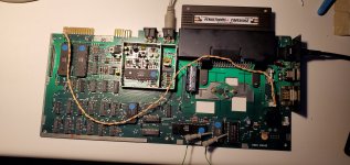
I posted this earlier and have been trying to resolve this issue.

The symptoms I'm noticing (Wavy video and hum in audio) is described here as being either the fault of the bridge rectifier or the voltage regulator.
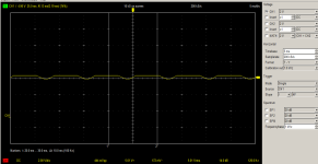
Hooking up the computer to the oscilloscope the output of the bridge rectifier is a flat voltage yet the output of the voltage regulator and also the 5 volt pin on the user port has a wave in it at (what my scope is reporting) 120 hz (see image below).

According to the link above at retroisle.com the regulator is an LM323K however looking at the schematic at zimmers.net (I'm going by the three tiffs near the bottom, for voltage regulation specifically: "vic20-left.tiff") the voltage regulator is an SI-3554M. And then there's what's actually in this system which is neither: SH323SC.

Of course in typical Commodore fashion they probably just used whatever they had or maybe someone had replaced it at some point.

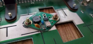
I have found a modern replacement for the LM323K which looks like a buck converter in a form factor that would serve as a drop-in replacement for this part.

Before I go that route though I thought I'd see if someone more knowledgeable with electronics might have some input. First I haven't entirely ruled out the bridge rectifier. Although the diodes seem to be working (voltage is only travelling in one direction) the output seems low, I would expect 9 volts DC but I'm only getting a little above 5. Yesterday when I tested it I was getting around 7 volts output so maybe the bridge rectifier is flaky and not providing enough voltage for the regulator to do its thing.

For reference here is what I'm seeing on the 5 volt line measured at the user port:
vic-20 5 volt line.PNG
 
The AC mains voltage is full-wave bridge rectified. This will convert the 60 Hz main into 120 Hz.

It is unlikely to be the voltage regulator - but we can't rule that out. It could be the smoothing capacitor(s) (C1 and/or C3) or a higher-than-normal current consumption of the logic.

Before we go off down a rabbit hole though, what is the actual voltage of the peak and trough of the signal?

You will expect some ripple on the power supply line. The question is "is it excessive".

517 mV I will assume (hope) equates to 5V +/- 260 mV.

The 5V rail is generally considered to be on the limit if you are getting 4.75 V (minimum) to 5.25 V (maximum).

What do you observe when you measure the voltage across C1 and then C3? Are they the same or different?

The input voltage to the voltage regulator does look a bit too low. You require +7.5V absolute minimum for the voltage regulator to work correctly.

A dumb question, you have measured the 'raw' 9V AC input voltage itself?

Dave
 
Last edited:
Incidentally, the three voltage regulator numbers you quote:

LM323K (Texas Instruments).
SI-3554M (Sanken).
SH323SC (Fairchild).

Are all 5V, 3A TO3 metal voltage regulators - just from different manufacturers (hence the different letters and numbers). They are all (largely) compatible with each other in this application.

Even though the schematic indicates one particular part, the internal BoM (Bill Of Materials) may have multiple suppliers with different part numbers.

As you say, they yours could have been replaced at some point in its life.

Dave
 
I have found a modern replacement for the LM323K which looks like a buck converter in a form factor that would serve as a drop-in replacement for this part.
I've installed that exact part in two of my VIC-20s, and so far they've been working great.

20210311_175801.jpg

Initially, I was warned that these would add more noise into the 5V rail, and it was recommended that I add extra capacitors to help smooth things out...
20190601_130819.jpg

Which proceeded to make whatever negligible ripple they had worse, so I removed the extra caps. Just let these regulators do their thing, it will be fine.

I can recall encountering at least 2 other people performing similar modifications on their VICs (one was from EZSBC like mine, the other was from a different manufacturer), and they've had similar success. The resulting reduction in heat output is staggering! You can run a VIC modified like this for hours on end, and will barely be able to tell that the machine is on just from the heat output.
 
Before we go off down a rabbit hole though, what is the actual voltage of the peak and trough of the signal?

You will expect some ripple on the power supply line. The question is "is it excessive".

517 mV I will assume (hope) equates to 5V +/- 260 mV.

The 5V rail is generally considered to be on the limit if you are getting 4.75 V (minimum) to 5.25 V (maximum).

What do you observe when you measure the voltage across C1 and then C3? Are they the same or different?

The input voltage to the voltage regulator does look a bit too low. You require +7.5V absolute minimum for the voltage regulator to work correctly.

A dumb question, you have measured the 'raw' 9V AC input voltage itself?

Dave

I've taken a few more measurements, here's what I'm seeing with a multimeter:

The power coming out of the power supply while disconnected from the VIC-20 (no load) is 10.3 volts
The A/C voltage at the rectifier (this time) is 7.4 volts (maybe I didn't have a good contact on my probes this morning?)
The D/C output of the rectifier is 6.86 volts.
The D/C output of the regulator is 4.9 volts.
The D/C voltage at the 5 volt line on the userport is 4.88.
C1 and C3 are both at 4.83

Now for the scope measurements:
D/C Output of the rectifier is 5.13 volts (so some disagreement there between the MM and the scope). No ripple a completely flat line.
On the scope I'm seeing the same wave on C1 and C3 as I am on the 5 volt pin of the user port.

Capture.PNG


At the bottom it is indicating 444 mV peak to peak (if I'm reading that correctly)

For all I know this all could be completely normal measurements for this system but given the screen waving, hum in the audio, and the color phasing this seemed like the most likely cause.
 
If the AC voltage (under load) at the input to the full-wave bridge rectifier is 7.4 Volts, you should observe 7.4 V * 1.414 = approximately 10.4 V DC at the output of the bridge rectifier.

You are reading 6.86 V. This is barely adequate for the voltage regulator.

According to the schematics, C1 should be at the INPUT of the voltage regulator and C3 at the OUTPUT of the voltage regulator. So the voltage reading for C1 does not seem consistent with the voltage reading from the output of the bridge rectifier.

The +5V rail sort of looks OK, but I am surprised by some of your AC and DC readings ahead of the voltage regulator though. This could be contributing to your problems.

I have to go out for the evening.

Dave
 
Hmm maybe I'm measuring the wrong capacitors, C1 and C3 are way over on the other side of the board by the keyboard connector.
 
Last edited:
alright I see the caps you are referring to on my board (REV F) they are C39 for the 4700uf/16v and c44 for the 100uf/16v
c39 is at 5.13v (no ripple)
c44 is at 4,94 with the ripple
 
I can recall encountering at least 2 other people performing similar modifications on their VICs (one was from EZSBC like mine, the other was from a different manufacturer), and they've had similar success. The resulting reduction in heat output is staggering! You can run a VIC modified like this for hours on end, and will barely be able to tell that the machine is on just from the heat output.

My Bridge Rectifier is actually getting much hotter than my voltage regulator is. I don't know how much heat should be expected from the BR and I am assuming if the VR was getting the correct input voltage it would probably get warm as well but as it is it's pretty cool to the touch.

I see in your pics your BR does not have a heat sink on it, how hot does it get?
 
Are you sure you don't have a shorted diode in the bridge rectifier?

If something is getting hot, it means it is dissipating power - which (in my book) indicates something is potentially wrong (especially given the low voltages we are seeing ahead of the voltage regulator).

Assuming your C39 is the capacitor on the input to the voltage regulator, at +5.13V DC that is just way too low to adequately supply a +5V voltage regulator with.

Dave
 
Last edited:
I don't see any shorts on the rectifier. I tested with a multimeter in continuity mode and confirmed power is only flowing one way however the resistance does seem pretty high (about 550 ohms) I don't know if that's expected or not.
I was assuming that the rectifier is intended to get a little hot since commodore had put a large heat sink on top of it with a bit a thermal paste.
I guess I could desolder C39 and test it in isolation just to rule that out.
 
Last edited:
550 Ohms does seem a bit high to me. This could indicate an internal open circuit rather than a short circuit.

The presence of external components would operate to decrease the resistance reading (not increase it).

I assume you have checked all four diodes of the bridge rectifier in both directions?

In the forward (current conduction) direction, the resistance of the diodes should be very low.

In the reverse direction, the resistance should be very high, or limited by the presence of the external VIC-20 components (especially the transformer).

When I was refurbishing my Cromemco Z2 power supply, I had the power supply all disassembled on the living room floor (I won't say what the wife said). I got everything working. After I reassembled it, no +8V... In between testing it and reassembling it, the bridge rectifier had gone open circuit! A quick trip to the electronic store (when we had one) sorted the problem. I just couldn't believe the timing of the failure though!

Dave
 
Yeah I tested all 4 diodes in both directions. In the forward direction each is giving me 568 ohms and in the reverse direction there's no measurable current at all. Maybe I should desolder and test it out of circuit?
 
Okay, I've desoldered the rectifier and took some measurements. The resistances are the same but if I pump the 10v/ac into it and measure the output I'm getting 9.28v/dc output. But then again there's no load except for the rectifier itself. I guess since I've already done the hard part (desoldering the rectifier) I might as well see if I can source a replacement and see how that goes.
 
10V [what] going in? 10V AC RMS?

Did you put a smoothing capacitor on the bridge rectifier output? If not, the output DC voltage will read low.

10V RMS input should give circa 13 V (ish) DC out.

Dave
 
It looks simply like the filtered voltage on the bridge rectifier output is troughing down, below the regulator's minimal input voltage, so that the troughs are breaking trough to the regulator's output. You can confirm this with a scope recording, with the scope on DC coupling connected to the bridge output and showing where the zero volt line is, you will probably find that the voltage troughs down below about 7v. Probably, you could ameliorate this with increase filter capacitance value directly on the bridge rectifier output. And probably if you had a Variac and cranked the line voltage up to 10 to 15% higher that what is is, the ripple would vanish.

The resistance you see on the meter testing a diode, is not an Ohms measurement. The value has little meaning. The diode tends to drop a specific forward voltage drop at some current. How the meter interprets that on the Ohms range depends on the design of the meter. You can test the diodes in the bridge with a diode test function on a typical DVM, and it will display a voltage drop, not a resistance.

PS: I wouldn't put those switching regulators in any of my vintage computers. The reason being that the original analog types have multiple safety features that prevent damage to downstream chips if the regulator fails or if there are overloads, shorts or overheating. I'd rather have the extra heat dissipation of the analog regulator and know that all the chips on my vintage boards were safe. You should read up on the design of analog regulators , such as National's LM309k and others invented in the late 60's and early 70's, they were a masterpiece of conservative design and safety. Don't worry about the extra heat unless you are living in Jamaica without air conditioning. Or if you are concerned fit an auxilary cooling fan
 
Last edited:
You can confirm this with a scope recording, with the scope on DC coupling connected to the bridge output and showing where the zero volt line is, you will probably find that the voltage troughs down below about 7v.
Hmm interesting, but when I put the scope on the output of the BR I wasn't getting any troughs, only a flat DC voltage.

I guess it's possible that the power supply that would have shipped with this VIC-20 and is intended for it just simply put out a higher voltage than the two I'm trying to use.
On the bench I'm using one labeled as 9 volt AC but actually puts out 10 (no load), I also have another one I can use which is labeled as 9 volt AC but puts out 15 with no load. I haven't tried using this yet.
In my office where I would normally use the VIC-20, I'd be using my ray carlsen C64/C128 power supply with a home-made adapter to take just the 9 volts AC and put that into the VIC-20, under no load it's measuring 9.6 volt AC (but this is a switch mode power supply)

Maybe this VIC's power circuity simply assumes a higher input voltage?
 
9V AC (assuming we are talking about an RMS and not a Peak reading) should be perfectly adequate for the VIC-20 - assuming the transformer is for the rated current (up to 3A).

If the power supply is rated for (say 1 or 2 A) then the voltage from the transformer will drop under load.

You have always mention voltage - but never the current or power rating. You can't have one without the other...

Dave
 
Ah that must be it then, both of these two power supplies are only rated for 1A (1000mA). I said I had a third which was outputting 15 volts but I must have been imaging things or that was in an alternate timeline or something because I can't find it now.

I guess I'll be hunting around for a 9 volt AC transformer with a higher current rating.
 
Man it is incredibly difficult to google for an AC adapter or transformer because 99.9% of the results are DC power supplies. People just use the term "AC" as meaning, "something you plug into the wall". However I did find this, a bit pricey but at least it looks like it would work once I replaced the end on it.
 
Back
Top