• Please review our updated Terms and Rules here

Exidy Sorcerer with Liveport FDM 180

IanB

Member
Joined
Mar 9, 2016
Messages
20
Location
UK
I acquired an Exidy Sorcerer with Liveport FDM 180 and several ROM PACs some time ago but it was DOA.
Recently I found some time to look at it and managed to get it working after replacing 8 chips (one DRAM, four 2114 SRAMs, one TTL and two ROMS) plus one of the rectifier diodes failed while I was working on it.
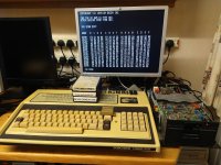

Exidy.jpg

(I've added an Exidy Sorcerer profile to the latest release of RGBtoHDMI)

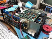
I'm now looking at the Liveport FDM 180 drive but there seems to be very little info on that device.
The only references I could find to that are on here and a similar thread on stardot, both started by JonB:


Initially the Liveport blew a tantalum capacitor on first power up but after replacing that and using deoxit on all the connectors I managed to view the boot ROM at 0xDC00 and it looks like it matches the known good image posted by exidyboy in the above thread.
When trying to run the boot ROM using GO DC00 the drive light comes on and the head loads which seems to indicate that it might actually work.

However I don't have any floppy disks for it so I'm stuck for the moment.

A few questions for anyone that might be able to help:

When I first opened up the Liveport, all the DIP switches were set to OFF which I think would have put the boot ROM at 0x0C00 which is in the RAM area so I set it to the same as JonB's one in the above thread (i.e. SW3 and SW8 set to ON)
With this setting the Sorcerer hangs on bootup but when I set SW8 to OFF I could read the ROM and start it as above so does anyone have any info on the DIP switch settings?

The drive is a Micropolis 1015-2
When a floppy disk is inserted, the drive spins continuously. Is this expected behaviour?
Also the door latch is not working properly so are there any tips on repairing that?

I understand this drive is 100TPI rather than the standard 96TPI so I won't be able to create a disk from an image using another drive and would have to create a disk from an image using this drive. Is that correct?

Is this hard sectored or soft sectored?
If it's hard sectored do any of the imaging systems like kryoflux or greaseweazle work with that?

Are there any boot images available for this system and can any of the drive emulators (Flash floppy or HXC) be used in place of this drive for initial testing?
(I see there are standard Exidy boot images but would they work with this system?)

I have contacted JonB but he sold his system some time ago.
 
Last edited:
I acquired an Exidy Sorcerer with Liveport FDM 180 and several ROM PACs some time ago but it was DOA.
Recently I found some time to look at it and managed to get it working after replacing 8 chips (one DRAM, four 2114 SRAMs, one TTL and two ROMS) plus one of the rectifier diodes failed while I was working on it.

Splendid, another one lives!

However I don't have any floppy disks for it so I'm stuck for the moment.

See below - I've imaged all of my Sorcerer disks as well as the ones with the machine I picked up for Exidyboy a couple of years ago.

A few questions for anyone that might be able to help:

When I first opened up the Liveport, all the DIP switches were set to OFF which I think would have put the boot ROM at 0x0C00 which is in the RAM area so I set it to the same as JonB's one in the above thread (i.e. SW3 and SW8 set to ON)
With this setting the Sorcerer hangs on bootup but when I set SW8 to OFF I could read the ROM and start it as above so does anyone have any info on the DIP switch settings?

No, but the FDM180 I have here also has all switches off and it's paired with its Sorcerer so now that I have that machine running again I can set it up with the drive and see what location it uses to boot.

The drive is a Micropolis 1015-2
When a floppy disk is inserted, the drive spins continuously. Is this expected behaviour?

Yes. It's the same unit found in my own dual-Micropolis stack I have with my own Sorcerer and that spins continuously too. It was the default behaviour of 8" drives originally - the motor kept spinning and to read/write the head solenoid would engage with the disk.

Also the door latch is not working properly so are there any tips on repairing that?

Got any pics? The drive is the same mech as used in the CBM 8050 drive for the PET - you insert a disk then push the door down to engage with the heads. When you push again to disengage the heads you then have to lift the door further up to release the disk.

I understand this drive is 100TPI rather than the standard 96TPI so I won't be able to create a disk from an image using another drive and would have to create a disk from an image using this drive. Is that correct?

Kind of. You can't read/write the actual disks in anything other than the FDM180. Since the drive is a standard Shugart mech though you can hook it directly up to a Greaseweazle (v3 in my case) after disconnecting all the liveport boards. I didn't use the GW client software for imaging though, I used David Given's Fluxengine client since it directly supports Micropolis disks.

LiveportFDM180greaseweazle.jpeg

For my own images I used the Micropolis stack that came with my machine.

Is this hard sectored or soft sectored?
If it's hard sectored do any of the imaging systems like kryoflux or greaseweazle work with that?

Hard sectored, 16 holes, and I don't know yet. Reading was fine and straightforward but I haven't tried going the other way and writing a disk because I don't have any spare hard sector ones. It used to be possible to buy punches that would add 15 extra holes to a standard cookie but I haven't checked on their availability for years. For my own Sorcerer I bought a Virtual Sector Generator from Mike Douglas and got it to boot soft sectored copies of the original CP/M disks. Check here: Sorcerer disk imaging. Drive I used was a 1.2mb 96TPI Mitsubishi MF504C. This meant the original hard sector disk was read on the 100TPI drive but written to a soft sector disk using a 96TPI drive.

Are there any boot images available for this system and can any of the drive emulators (Flash floppy or HXC) be used in place of this drive for initial testing?
(I see there are standard Exidy boot images but would they work with this system?)

I have contacted JonB but he sold his system some time ago.

In typical 'me' fashion I can't remember where I put my disk images, but once I do I'll put them on my Sorcerer page. Another thing I was going to do was see if the machine would boot with a Gotek. For FlashFloppy you need to use HFEv3 format to support hard sector images. I'm hoping the Fluxengine client has encoded the index pulses in the raw disk image so the HxC Emulator will be able to write HFEv3 images off the back of it.

Cheers,
 
See below - I've imaged all of my Sorcerer disks as well as the ones with the machine I picked up for Exidyboy a couple of years ago.

Thanks for replying, that's good to know

Got any pics? The drive is the same mech as used in the CBM 8050 drive for the PET - you insert a disk then push the door down to engage with the heads. When you push again to disengage the heads you then have to lift the door further up to release the disk.

I managed to fix it:

First I used isopropyl alcohol to dissolve as much of the existing grease as I could because it had become very thick and sticky and then I re-greased the latching mechanism and after manually rotating the mechanism a few times to spread the new grease it started working again.

Kind of. You can't read/write the actual disks in anything other than the FDM180. Since the drive is a standard Shugart mech though you can hook it directly up to a Greaseweazle (v3 in my case) after disconnecting all the liveport boards. I didn't use the GW client software for imaging though, I used David Given's Fluxengine client since it directly supports Micropolis disks.

I have a Greaseweazle v4, would that be OK?

Hard sectored, 16 holes, and I don't know yet. Reading was fine and straightforward but I haven't tried going the other way and writing a disk because I don't have any spare hard sector ones. It used to be possible to buy punches that would add 15 extra holes to a standard cookie but I haven't checked on their availability for years.

It occurred to me that if I could get a scan of a hard sectored 'cookie' I could print that out actual size and use it as a template to punch holes in a soft sectored floppy but I don't know if that would be accurate enough.

For my own Sorcerer I bought a Virtual Sector Generator from Mike Douglas and got it to boot soft sectored copies of the original CP/M disks. Check here: Sorcerer disk imaging. Drive I used was a 1.2mb 96TPI Mitsubishi MF504C. This meant the original hard sector disk was read on the 100TPI drive but written to a soft sector disk using a 96TPI drive.

Would the Virtual Sector Generator work on the original Micropolis drive? I don't have any hard sectored disks so converting the original might be the best option if it will work.
Also can the Micropolis drive be used as a normal soft sectored drive on other systems for testing or is it non standard in other ways as well as the TPI? (i.e is the hard sectoring a function of just the controller or does it need a special drive as well)

In typical 'me' fashion I can't remember where I put my disk images, but once I do I'll put them on my Sorcerer page. Another thing I was going to do was see if the machine would boot with a Gotek. For FlashFloppy you need to use HFEv3 format to support hard sector images. I'm hoping the Fluxengine client has encoded the index pulses in the raw disk image so the HxC Emulator will be able to write HFEv3 images off the back of it.

It might be useful if you could confirm that booting with a gotek was possible or document your soft sectored boot imaging procedure above as at the moment there are too many unknowns if things don't work. (i.e could be faulty controller, faulty drive, imaging problem etc.)
 
>> It occurred to me that if I could get a scan of a hard sectored 'cookie' I could print that out actual size and use it as a template to punch holes in a soft sectored floppy but I don't know if that would be accurate enough.

I roll my own 16 hard-sector floppies from soft sector NOS floppies. After some (ok, a lot) of experimenting I found you need precise, sharp and even pressure to punch the hole, otherwise you tend to get a small burr in the mylar cookie/biscuit. That burr causes the floppy liner to catch and tear over time, and it generally sounds terrible in use. A steel punch, mylar biscuit in the middle, softer metal below seems to work best. I make the spacing accurately these days, but surprisingly in the past, a +-1 mm variation between sector holes still worked (at least on the same drive). Let me know if you would like some I've already made or further advice on how to make your own.
 
Would the Virtual Sector Generator work on the original Micropolis drive?
Yes and also with a Gotek.
Also can the Micropolis drive be used as a normal soft sectored drive on other systems for testing or is it non standard in other ways as well as the TPI? (i.e is the hard sectoring a function of just the controller or does it need a special drive as well)
The only difference is the TPI. The Exidy FDS (Floppy Disk Subsystem), which was a solution that dispensed with the need for the S-100 Expansion Unit, used a 100TPI drive, and the drive itself is interchangeable with a drive in a Liveport or in a standalone enclosure connected to an S-100 floppy disk controller like the Micropolis card.
 
In typical 'me' fashion I can't remember where I put my disk images, but once I do I'll put them on my Sorcerer page.

I've been looking at your Sorcerer page and see you have a heavily modified machine including a colour graphics card but no information on the card:

I vaguely recalled some sort of colour graphics board and the Stuart name and after looking at some old magazines I think I have found the product in question:

micrographics-ct-.png

It looks like it was originally designed for the Nascom I but later adverts indicated Superboard, Nascom II and UK101 support and I remembered looking at this product at the time as I had a UK101.
The advert mentions that it could be adapted to other machines so I guess that's what happened in this case as I never found any advert mentioning the Sorcerer.

Based on the above description and your photos which show a board with only nine TTL chips and no memory I could take a reasonable guess as to how it works:

It seems to be designed to work with a character cell based video system and is connected to the 8 bit output of the video RAM.
Those 8 bits per cell are decoded as 4 bits for the pixels, 3 bits for the colour and 1 bit to control switching between the colour graphics and the original text based on the following:

The advert mentions "Over 3000 colour cells" and later adverts mention 3072. The UK101 and Nascom I/II had 48x16 displays which works out as 4 pixels per character cell so 4 bits per byte for an overall resolution of 96x32 or maybe 48x64 although in the case of the Sorcerer it would be higher due to the higher text resolution.
Eight colours means 3 bits per byte for the colour of the pixels in the cell
Finally the editorial text on the left mentions overlaying the original text on the graphics so I assume the top bit of each byte was used to switch between the original text output and the colour graphics output athough I'm not sure if that was implemented in your system as it looks like it is using a separate output for the graphics. (The top bit was unused on the Nascom I which was the original machine for the product)

Maybe you could post some hires photos of the front and back of the board so the schematic could be reverse engineered.
 
Last edited:
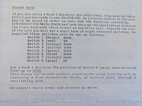
Hi all! Just so you know, I've currently got JonB's FDM 180, sitting in a very large pile of things I REALLY must fix. Here's what the 'Brief Installation and Operating Instructions' have to say on the subject of the DIP switches ...

PXL_20230524_191740161.jpg
 
Hi all! Just so you know, I've currently got JonB's FDM 180, sitting in a very large pile of things I REALLY must fix. Here's what the 'Brief Installation and Operating Instructions' have to say on the subject of the DIP switches ...
Thanks for that.
It confirms that switching SW8 off for a Mark 1 Sorcerer like mine is correct and not an indication of a fault.

Could you post the rest of the instructions if possible (photo or scan)
 
I've been looking at your Sorcerer page and see you have a heavily modified machine including a colour graphics card but no information on the card:

I vaguely recalled some sort of colour graphics board and the Stuart name and after looking at some old magazines I think I have found the product in question:

View attachment 1257972

It looks like it was originally designed for the Nascom I but later adverts indicated Superboard, Nascom II and UK101 support and I remembered looking at this product at the time as I had a UK101.
The advert mentions that it could be adapted to other machines so I guess that's what happened in this case as I never found any advert mentioning the Sorcerer.

Based on the above description and your photos which show a board with only nine TTL chips and no memory I could take a reasonable guess as to how it works:

It seems to be designed to work with a character cell based video system and is connected to the 8 bit output of the video RAM.
Those 8 bits per cell are decoded as 4 bits for the pixels, 3 bits for the colour and 1 bit to control switching between the colour graphics and the original text based on the following:

The advert mentions "Over 3000 colour cells" and later adverts mention 3072. The UK101 and Nascom I/II had 48x16 displays which works out as 4 pixels per character cell so 4 bits per byte for an overall resolution of 96x32 or maybe 48x64 although in the case of the Sorcerer it would be higher due to the higher text resolution.
Eight colours means 3 bits per byte for the colour of the pixels in the cell
Finally the editorial text on the left mentions overlaying the original text on the graphics so I assume the top bit of each byte was used to switch between the original text output and the colour graphics output athough I'm not sure if that was implemented in your system as it looks like it is using a separate output for the graphics. (The top bit was unused on the Nascom I which was the original machine for the product)

Maybe you could post some hires photos of the front and back of the board so the schematic could be reverse engineered.

Hi Ian,
I have been through my archives and have found an article entitled "Technicolour (sic) for the Exidy" by Pete Scargill from SPEC (Sorcerer Program Exchange Club) Issue 6, January 1980, talking about his experience with the Stuart Micrographics colour graphics board in an Exidy Sorcerer. The SPEC newsletter was the later renamed to ESCape (European Sorcerer Club).
 

Attachments

  • SPEC_6_jan_1980_technicolour_sorcerer_stuart_micrographics.pdf
    416.8 KB · Views: 8
Back
Top