• Please review our updated Terms and Rules here

front panel graphics generation - what software do you use?

DougM

Experienced Member
Joined
Apr 20, 2023
Messages
173
Location
Bellevue, WA
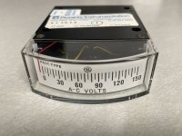
I'm trying to create some faux vintage analog meters, sort of like this
1730597157475.jpeg
except instead of the needle moving the needle stays in the middle and the scale rotates. My google fu completely failed me in finding a picture of one.

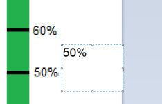
But that's not actually important to my question which is . . . what (Windows) software do you use when laying out labels? I've tried Paint and while it works pretty well, for some reason it pixelates the font right after I place it.
1730597299541.png

in this image you can see the font right before I hit enter (in the dashed box) and after I hit enter (next to the scale)

There are a lot of graphics programs out there but the learning curve is petty intimidating. What do you folks use?

I'm using a Canon Selphy to print them - it works great except it almost always glitches somewhere, so I have to print multiple scales to get one perfect one.

Thank you,
 
I suspect what's going on is that you're zoomed in.

The text area might be, say, 64 pixels high on screen, but only 16 in the file.
So, while you're editing the text, it can render it with 64 pixel high fonts that are smooth, but when it records it to the actual file, it renders it with 16-pixel fonts, and zooms it back up to 64 pixels, creating blockiness.

Make the image several times "true size" and scale down to fit, or perhaps consider vector-oriented software like Inkscape instead, that will preserve smooth curves and scale as needed.
 
OpenSCAD's text() command will do it. You can put the marker lines and text exactly where you want, calculated programmatically so the resulting scale label is the exact physical size you require. Then export to DXF, SVG or other formats. For instance opening in Inkscape.
If you have any knowledge of programming or scripting It's not difficult to learn.
 
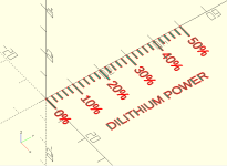
I had a go at generating a simple scale label in OpenSCAD, results as shown.

The code. Download OpenSCAD (FOSS from openscad.org) then paste in the following text in the left-hand pane, then press F5 to preview then F6 to render.

Code:
// OpenSCAD script to draw graduation ticks and half-length ticks for a gauge label
// Percentage labels placed at full ticks
// Last updated    20241103

// Adjust as required. All dimensions in mm
GRAD_SPACING = 2;
GRAD_COUNT = 25;
GRAD_LINEWIDTH = 0.5;
MAJOR_TICK_EVERY = 5;
MAJOR_TICK_LENGTH = 5;
SHORT_TICK_LENGTH = 3;
TEXT_SIZE = 3;

// Graduations
for (y = [0 : GRAD_COUNT])
    translate([0, y * GRAD_SPACING - GRAD_LINEWIDTH/2])
    {
        square([(y % MAJOR_TICK_EVERY ? SHORT_TICK_LENGTH: MAJOR_TICK_LENGTH), GRAD_LINEWIDTH]);
        // Major tick labels
        if (y % MAJOR_TICK_EVERY ? 0 : 1)
            translate([TEXT_SIZE * 2, -TEXT_SIZE / 2])
                text(str(y * 2, "%"), size=TEXT_SIZE);
    }

// Main label
translate([22, MAJOR_TICK_EVERY + TEXT_SIZE])
    rotate(90)
        text("DILITHIUM POWER", size=TEXT_SIZE);

The result looks as follows. The major axis ticks are 10mm
test_label.png


Result 0% to 50% along Y axis is 50mm wide as desired, so export to DXF or SVG with File | Export.


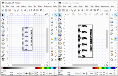
The resulting DXF and SVG opened in two instances of Inkscape side by side. The grid dot spacing for both is 5mm. Note the extra allowance Inkscape as added to encompass the text in a bounding rectangle.

test_label_DXF_and_PNG_scale_test.png
 
Last edited:
Thank you! Inkscape looks to be the solution I'm after, but I'll also take a look at OpenSCAD.

I'll post some pictures of the end result.
 
Since we were discussing AI in a different thread it suddenly occurred to me that I should just ask AI to create the graphic for me.

Didn't work worth a damn.
 
  • Haha
Reactions: cjs
Inkscape works well for SVG but it is a bit buggy so I recommend saving your work often.
 
Back
Top