Hello,
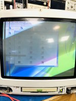
I have never seen a CRT/TV do this before (I used to work in TV repair, but that was in the late 70s through 1983, so I am a tad rusty). I replaced the flyback and horz output to get this iMac to come on. The unblanking has vertical strips in it, missing video. This one had worked almost perfectly until the first time I turned it off (it was having display size jittering, and some flashing, so I assume the flyback was failing). I doubt the CRT got damaged while sitting on the floor of my storage room for a week or so. I have no idea if this could be the video out of the computer board or the display board. I checked all display board caps before replacing the flyback and horz output. If I changed the OS resolution down to 800x600, the blank vertical lines are still there. Could be a yoke, but the mouse passes through the blank line, like they still there. If I move a window, the window doesn't jump across the lines. So it kind of looks like a really weird un-blanking issue. I cannot find schematics for this thing anywhere.
The original flyback was: 6174Z-1017D. The flyback from the parts unit (can not be sure it is 100%) is a 6174Z-1003D. From what little I have found on-line, the 6174Z-1003D is used to replace a 6174Z-1017D.
When the original flyback (6174Z-1017D) was working no lines. With the used 6174Z-1003D on the board, there are lines that are effected only by the screen control. I ordered a new 6174Z-1003D from EBAY for $41. Not a huge loss if it doesn't fix the problem. I don't know how the flyback could be causing this. Oh and if I resize the image via the monitor settings in the control panel, the lines move with the re-sizing, so that rules out the CRT.