• Please review our updated Terms and Rules here

Getting a DTK Peer-2030 computer running

Coincidentally, I am now sometimes seeing something similar with my IBM CGA card, and I think, "Is that a video RAM chip on its way out?"
Oh, yeah. Just like the root cause analysis for my Compaq Portable 1 a few months ago. :)


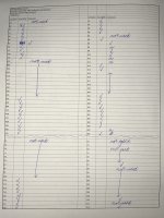
Here's the Peer-2030 motherboard diagram. I numbered the slots myself, left to right as seen from the front of the computer. This may or may not be opposite general convention.

Slots 2, 3, 4, 5, 6, and 8 are 16-bit.
Slots 1 and 7 are 8-bit.

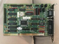
Slot 8 is the slot the controller card started in. Slot 2 is where the 16-bit video card is. Slot 1 is where I intend to put the 8-bit sound card once I get this unit fully operational. 🎶

I suppose my next step is to start checking continuity from the edge connectors of the controller card to the soldering points that each of them first go to. There are also many sets of wires that come from the front panel of the case to headers on the controller card. I should also double-check that each of those is correct. Some are for the turbo button, turbo LED, power LED, HDD LED, maybe the key, etc. Maybe one or more of them are for something impacting this.

1664478436712.png
 
Last edited:
Update.

There are also many sets of wires that come from the front panel of the case to headers on the controller card. I should also double-check that each of those is correct. Some are for the turbo button, turbo LED, power LED, HDD LED, maybe the key, etc. Maybe one or more of them are for something impacting this.
I misspoke. There is only one such wire header on the controller card that leads to the case front panel. That is a 2-contact header that likely goes to the HDD LED. All the other headers I mentioned are on the motherboard.

I've attached photographs of the controller card. The printing says it is a MIO-400KF rev. C. An eBay listing says it was made by Acer, and so does the central chip. Here is its listing at stason.org.

The edge connector contacts are labeled A1-A31, then C1-C18. Obviously, then, their counterparts on the flip side are B1-B31 and D1-D18.

Some of the contacts don't look like they have anything that leads from them. I checked continuity on all the others, following traces on the board until I either found a contact point or via, or had to guess among a cluster of them until one gave a beep. The only one that is suspect is A2.

Here is the pinout of a 16-bit ISA slot from Wikipedia. A2 is "data 7." Sounds logical to me, then, that this disconnection may be the source of the floppy drives not registering or seeking correctly.

Here is the pattern established at this cluster of 8 vias on the front of the board.
1664575901446.png

I am not 100% certain that the upper right via should lead to A2, but I am 99% certain. So my next step is to create a bodge from A2 to that via.

There is also good news that there are other units of MIO-400KF on eBay. Just in case.

Another question. The jumper settings from stason.org say JP3/H should be set to 2-3 to enable hard drive and JP3/I should be 2-3 to enable the game port (on a breakout panel). JP3 is in the upper left of the photograph. As I read the pin numbering, it looks like JP3/H and I are both set to 1-2. Am I reading that correctly?
 

Attachments

  • Controller card - IMG_6987.jpg
    Controller card - IMG_6987.jpg
    3.2 MB · Views: 6
  • Controller card - IMG_6988.jpg
    Controller card - IMG_6988.jpg
    3.2 MB · Views: 7
  • Controller card continuinty check table.jpg
    Controller card continuinty check table.jpg
    1.2 MB · Views: 4
So my next step is to create a bodge from A2 to that via.
doc-brown-bttf.gif

As soon as I turned on the switch with the new bodge in place, the computer gave no hesitancy at properly seeking the floppy drives, and then it immediately loaded DOS from drive A! Finally!

Next step: To get at hard drive working. I connected a Seagate ST3606A which already has DOS and several games on it. The BIOS allows custom geometries to be defined as type 48 and 49. I defined type 48 as CHS = (1223,16,63).
1664601519895.png

The boot-up now gives "Fixed Disk Controller Failure." I tried all 3 translations above with the same result and checked that the HDD connector ribbon cable is oriented correctly. Is there something else wrong with the controller card?
 
Another question. The jumper settings from stason.org say JP3/H should be set to 2-3 to enable hard drive and JP3/I should be 2-3 to enable the game port (on a breakout panel). JP3 is in the upper left of the photograph. As I read the pin numbering, it looks like JP3/H and I are both set to 1-2. Am I reading that correctly?
I don't think so. I think that all of the jumpers on your JP3 are set 2-3. I will explain why:

The first thing that I noticed is that your card and stason.org (a copy of Total Hardware 99) are using different conventions for JP3:

On your card, the JP3 pins are simply labelled pin 1 to pin 27.

Instead, stason.org shows rows A to J, with a failure to indicate within a row, which is pin1, which is pin 2, and which is pin 3. Because the options are either 'Pins 1 & 2 closed" or "Pins 2 & 3 closed", we can deduce that pin 2 is the center pin. So, of the other two pins in a row, which is 1 and which is 3? The stason.org page indicates that to enable the floppy functionality, both JP3/F and JP3/G need to be in the "Pins 2 & 3 closed" position. Your floppy functionality must be enabled because you see/hear seeking, and so therefore, both JP3/F and JP3/G are in the "Pins 2 & 3 closed" position.
 
The boot-up now gives "Fixed Disk Controller Failure." I tried all 3 translations above with the same result and checked that the HDD connector ribbon cable is oriented correctly. Is there something else wrong with the controller card?
From what was worked out in my previous post, the stason.org page, and the photo of your MIO-400, the hard drive controller functionality within the MIO-400 is enabled (i.e. JP3/H is in the 'Pins 2 & 3 closed' position).

Another slot problem ?

Can you test the MIO-400 in a different computer ?
 
Your floppy functionality must be enabled because you see/hear seeking, and so therefore, both JP3/F and JP3/G are in the "Pins 2 & 3 closed" position.
In post 23, I forgot to say that I had already moved JP3/H and JP3/I from the position I pictured. Headsmacker moment. I have moved them back. The hard drive works now. Thanks.

The next two steps are adding the 8-bit sound card and maxxing out the memory. The sound card is easy. Except I think I will use an 8-bit SoundBlaster for this one instead of the 8-bit Aztech. Here is a picture of one of the two memory sticks. If I go searching eBay for 2 more of these for the 2 empty slots, what should I search for, and what do I have to make sure the listing says and does not say?
1664635019325.png
 
Last edited:
From the PEER-2030 manual:

• "Choice of either 44256 DIP or 256k/1M SIMM DRAM modules with 80ns"

( Less than 80 ns rated RAM is fine. )

• Pages 8 through 17 of chapter 2 ('Setting Up Your System') concern the various options/configurations for motherboard RAM.
SIMMS: The drawings of SIMM's contain 9 chips, informing us that they are the type have parity (i.e. 8 data + 1 parity).
SIMM's: 30-pin.

You presently have two 1M SIMM's (a bank on your motherboard), and possibly some DIP's. Looking at table 2-3 in the manual, your present configuration is either 2MB 'Total System Memory', or 3MB 'Total System Memory', or 4MB 'Total System Memory'. That and your "for the 2 empty slots" suggests that you have a 3MB configuration (now aiming for a 5 MB configuration).

So, you are after 1 MB sized 30-pin parity SIMM's of 80 ns (or less) access time. Someone more knowledgeable on SIMM's might add/comment to that.
 
I'm still confused and would like to give more details of what it currently looks like, and ask questions, to understand the situation.

The RAM test gives the following.
  • Base RAM 640 kB.
  • Shadow RAM 384 kB.
  • Extended RAM 1024 kB.
After booting from a floppy disk, the MEM command gives the following.
  • Conventional 640 kB.
  • Upper 0 kB.
  • Reserved 384 kB.
  • Total 2048 kB.
Page 2-14, figure 2-11 shows the physical configuration I have. I don't think I have changed any of the memory. I think this is the state the memory was in when I acquired the computer a couple years ago.
  • As seen from the front of the computer (see manual page 2-8), the 2 leftmost slot banks are populated. Jumpers W1-W6 are all set to pins 1-2. There are no memory chips in the socket banks on the motherboard.
  • The picture above is the stick from the leftmost bank. Can anyone tell what size and speed RAM it is? How can you tell?
  • According to figure 2-11, the 2 existing sticks should be 411000, which Google says is 1 MB. But wouldn't that mean the total memory is 640 kB. + 384. kB. + 2*1 MB. = 3 MB., not 2 MB as the self-test and MEM commands say?
The manual also says on page 2-9 that the RAM also needs to be configured in the BIOS. Really? That seems primitive for a 386SX. Or is it talking about how the total memory gets allocated: upper/extended/etc.? But even if it means allocation, I thought that allocation was a matter for CONFIG.SYS and AUTOEXEC.BAT?

See manual page 2-9, table 2-3. What is wait state? What is page interleave? Do I need to worry about them at all? Do I need to worry about whether the turbo button is on, as that page says?

See manual page 2-16. It seems like all I need to do, then, to get to 4 MB. total RAM is: acquire two more 411000 SIMM DRAM modules at 80 ns. or faster with parity and 30 pins, put them in the 2 rightmost banks, and move W1-W6 all to pins 2-3. Is that correct?
 
The RAM test gives the following.
  • Base RAM 640 kB.
  • Shadow RAM 384 kB.
  • Extended RAM 1024 kB.
So, the BIOS believes that there is 2 MB total.

After booting from a floppy disk, the MEM command gives the following.

Conventional 640 kB.
Upper 0 kB.
Reserved 384 kB.
Total 2048 kB.
You must have accidentally omitted an 'Extended' line, one that we expect to indicate 1024 kB

Page 2-14, figure 2-11 shows the physical configuration I have.
2 MB, matching the above.

Can anyone tell what size and speed RAM it is? How can you tell?
Looking at the photo of one of your existing SIMM's:

Nine MT4C1024DJ-8 modules on the SIMM.
MT4C1024DJ = 1M x 1 bit = 1 Mbit
One of the MT4C1024DJ provides the parity bit.
Eight x 1 Mbit = 1 MB on the SIMM

The "-8" will mean 80 ns.

According to figure 2-11, the 2 existing sticks should be 411000, which Google says is 1 MB. But wouldn't that mean the total memory is 640 kB. + 384. kB. + 2*1 MB. = 3 MB., not 2 MB as the self-test and MEM commands say?
The 411000 is one of the nine modules on the chip.

1664873874786.png
411000 = 1M x 1 bit = 1 Mbit
So, same story as for your existing SIMM's.

The manual also says on page 2-9 that the RAM also needs to be configured in the BIOS. Really? That seems primitive for a 386SX. Or is it talking about how the total memory gets allocated: upper/extended/etc.? But even if it means allocation, I thought that allocation was a matter for CONFIG.SYS and AUTOEXEC.BAT?
For the CMOS SETUP:

- Informing the BIOS as to how much conventional (base) memory is present.
- Informing the BIOS as to how much extended memory is present.
- Configuration: What should the motherboard do with the 384 KB. Use for ROM shadowing? Use as extra extended memory? ....

CONFIG.SYS/AUTOEXEC.BAT:

For creating XMS memory, etc.

See manual page 2-16. It seems like all I need to do, then, to get to 4 MB. total RAM is: acquire two more 411000 SIMM DRAM modules at 80 ns. or faster with parity and 30 pins, put them in the 2 rightmost banks, and move W1-W6 all to pins 2-3. Is that correct?
Although the manual suggests SIMM's that contain 411000 modules; clearly MT4C1024 modules are okay (i.e. what is on your existing SIMM's).
As for W1-W6, figure 2-13 indicates that W1-W6 are to remain as they are.
 
You must have accidentally omitted an 'Extended' line, one that we expect to indicate 1024 kB
Correct.

How about this item on eBay?
1664934808263.png

How about this item on eBay?
1664934864771.png

If both of these will work in concert with the 2 existing, then that will give me a complete 4 MB. RAM for not much money.

Is there a natural incompatibility between "PC" memory sticks and "Apple" memory sticks, as given in eBay item titles? Or does computer OS not matter?

Is there such a thing as memory stick brand incompatibility? Like don't mix Energizer batteries with Duracells?
 
I am going to leave the answering of your questions in post #30 to someone more knowledgeable in that area.
I thought that someone else (more knowledgeable about SIMM's) may have answered by now.

So why did DTK put "411000" in the manual?
Perhaps they were suggesting, 'We tested our motherboard with SIMM's containing 411000 chips and they worked. We therefore recommend you use SIMM's containing 411000 chips.'
Perhaps 411000 were the only 1 Mbit chips at the time.
Don't know.

30-pin SIMM's are primitive, but there are no guarantees. If you want high probability of success, then go for parity SIMM's containing 411000 or MT4C1024 chips, because you know those work with your motherboard. But what you pointed to are relatively cheap. Do you take the chance?

Is there such a thing as memory stick brand incompatibility? Like don't mix Energizer batteries with Duracells?
From memory (pardon the pun), I don't think 'You must use matching sticks in a bank' applied until 72-pin SIMM's came along. They have Serial Presence Detect (SPD) so that the motherboard can query the SIMM for information such as capacity, timing, ... The motherboard would query the first SIMM in the bank, and assume that the other SIMM's in the bank were identical. The motherboard would then, via the chipset, adjust the memory timing (CAS latency, etc.) used for the bank based on the information that came back from the first SIMM. Something like that.

30-pin SIMM's do not have SPD, and therefore your motherboard does not use SPD. Your motherboard is simply expecting that SIMM's will be used that meet the motherboard's fixed timing.
 
I bought those two sticks. Here’s hoping.

Somewhere in my vintage inventory, I have some memory sticks, but I don’t know if they would be what is needed, nor do I recall where they are at the moment. My inventory from twice at Computer Reset and VCFMW plus several friends giving me old parts and equipment for free, all results in too much at the moment to coordinate. Time for me to reduce some inventory out to A Few Good Users.
 
The two separate sticks arrived today. I’ve installed them and am trying to figure out how to configure the computer for them. The self-test says “System memory mismatch.” So I enter the BIOS, which wants me to type in the extended memory number (“384, 512, 1024, 1536…”). It was set for 1024. I try 4096 but booting gives a memory mismatch. So does 2048. So does 3072. I have not moved the jumpers.
 
Last edited:
The two separate sticks arrived today. I’ve installed them and am trying to figure out how to configure the computer for them. The self-test says “System memory mismatch.” So I enter the BIOS, which wants me to type in the extended memory number (“384, 512, 1024, 1536…”). It was set for 1024. I try 4096 but booting gives a memory mismatch. So does 2048. So does 3072. I have not moved the jumpers.
Before (2MB configuration): 640 KB base + 384 KB shadow + 1024 KB extended.
Expected to see now (4MB configuration): 640 KB base + 384 KB shadow + 3072 KB extended.

The Peer-2030's POST does a RAM test very early, showing BASE/SHADOW/EXTENDED amounts. What figures are shown now?
 
The self-test shows:
Base RAM 640 kB.
Shadow RAM 384 kB.
Extended RAM 1024 kB.

These numbers are constant regardless of what number I type into the BIOS. The BIOS retains every setting I give it except the size of the extended memory.
 
If you already tried this I may have missed it, but one thing you may want to do is replace both of your original simms with your new simms, in the same configuration. That might help confirm that your new simms are working and compatible.
 
If you already tried this I may have missed it, but one thing you may want to do is replace both of your original simms with your new simms, in the same configuration. That might help confirm that your new simms are working and compatible.
I removed all 4 sticks, put the newly-arrived sticks in the first 2 slots, and rebooted. The self-test said there was a mismatch, I rebooted again, and it is fine. The MEM command shows 1024 kB. of extended memory. So the newly-arrived sticks must be working.
 
..... So the newly-arrived sticks must be working.
Good to rule that out.

The self-test shows:
Base RAM 640 kB.
Shadow RAM 384 kB.
Extended RAM 1024 kB.

These numbers are constant regardless of what number I type into the BIOS.
A question becomes, are those figures what the POST is discovering via a write-then-read-back discovery mechanism, or is it testing only the amounts recorded in the CMOS SETUP.

Before you added the two extra sticks to the two existing sticks, there was no memory mismatch error. As soon as you added the extra sticks, you saw the memory mismatch error. So we have to be confident that the POST is seeing the extra RAM. But with the 'Extended RAM' figure of the self-test remaining at 1024, then that indicates to me that the self-test only tests/displays the amounts recorded in the CMOS SETUP.

I have not moved the jumpers.
And from what I read in the motherboard's manual, there is no requirement.

1. Figures 2-11 and 2-13 both show jumpers W1-W6 in the same positions.

2. If we look at table 2-3, the present wait state and page interleave setting you have is {Wait State = 1}{Page Interleave = Disable}.
Looking at the three possible options for the 4MB configuration, the same setting works for the 4MB configuration as well, although for better performance, when you have the 4MB configuration going, try changing the setting to {Wait State = 0}{Page Interleave = Enable}.

The BIOS retains every setting I give it except the size of the extended memory.
There does appear to be something odd going on with changing your CMOS SETUP information. You mention it yourself back at post #13: "Memory mismatch. Like the display card mismatch, it seems that me going into the BIOS causes the memory to be sensed and then on subsequent boots, the error does not occur."

Need to do a cold boot, or two?
 
Hmm. I removed the 2 newly-arrived sticks, replaced the original sticks in their original slots, and put the 2 new sticks in the far slots. Rebooted and the self-test correctly detected 3072 kB. of extended memory and automatically input it into the BIOS. The MEM command shows 4096 kB. total memory. I suppose I just didn’t have the 2 new sticks making good contact the first time.

The last 3 upgrades I can think of doing are
  • adding a CD-ROM drive linked to the SoundBlaster 16 card, to populate that last 5.25-inch drive bay
  • adding a modem card (because why not?) 😉
  • adding a CF card adaptor for a removable drive D, so among all my inventory I need to find a Molex-to-Berg adaptor and a long enough IDE HDD ribbon cable.
 
Back
Top