• Please review our updated Terms and Rules here

Getting XT-CF-Lite/XT-IDE working

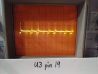
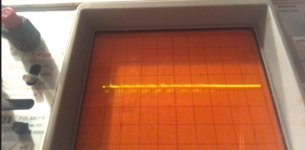
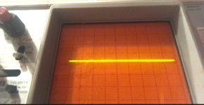
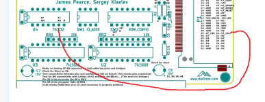
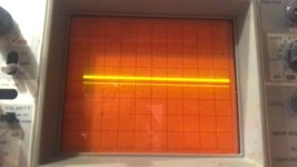
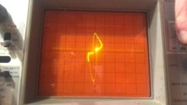
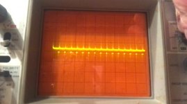
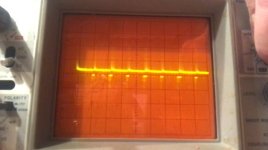
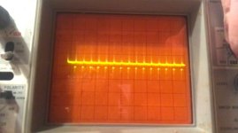
Five photos, one for each of the five steps:
No, you misunderstand. All 5 photos are of U3 pin 19. I only varied the time scale and maybe x-scale and y-scale. Before looking at any of the other pins, like you said, I wanted to see if there was a pulse at all at U3 pin 19. Is there a pulse?
Okay.
Yes, I see pulses there, and if you change one of the base I/O switches on the card (i.e. card no longer at 300h), pin 19 should then always stay HIGH (i.e. something over +2V DC).
 
Just a comment-
When I've hand soldered CF sockets, what I tend to do to check things is use something like an exacto knife to carefully nudge each pin and confirm the solder joint is good.
I also build with a 15x binocular microscope to look for solder bridges. Solder with LOTS and LOTS of FLUX and then clean it all off.

Careful visual inspection is also very important.

Buzzing out the PCB connectivity, as you know, is also key.

It is quite hard to verify signals on a CF connector. You run the risk of the probe straddling 2 pins.
 
Yes, I see pulses there, and if you change one of the base I/O switches on the card (i.e. card no longer at 300h), pin 19 should then always stay HIGH (i.e. something over +2V DC).
Yes, it was high. I didn't read the exact amount, but it was higher than the waveform.

IMG_20220407_221444215.jpg

1. Expect to observe pulses on pin 19 of the U3 chip. <--- No point in proceeding if these pulses are not present. Yes.
IMG_20220407_221610303.jpg

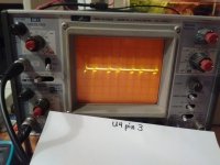
2. Expect to observe pulses on pin 3 of the U4 chip. Yes.
IMG_20220407_223503331.jpg

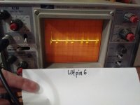
3. Expect to observe pulses on pin 6 of the U4 chip. Yes.
IMG_20220407_224101695.jpg

4. Expect to observe pulses on pin 7 of the CF connector. Yes.
CF pin 7.jpg

5. Expect to observe pulses on pin 32 of the CF connector. No; pin 32 appears flatline.
CF pin 32.jpg
 
According to the XTIDE board manual, pin 32 is CS1.

According to the SanDisk CF card datasheet,
  • -CS1 is only needed for 16-bit mode (page 3-2), and
  • "In the True IDE Mode -CS0 is the chip select for the task file registers while -CS1 is used to select the Alternate Status Register and the Device Control Register" (page 3-4), and
  • "Device address consists of signals -CS0, -CS1 and -DA(2:0)" (page 3-18)
Have we found the reason the CF cards are not recognized?
 
Expect to observe pulses on pin 32 of the CF connector. No; pin 32 appears flatline.
On pin 32 of the CF connector, you should be seeing the pulses that you see on pin 6 of the U4 chip, because the circuit connects those two pins together.
Puzzling, because earlier, you did the continuity test, and that test includes a continuity check between pin 6 of U4 and pin 32 of the CF connector.

On the right pin ?

(BTW. Your waveforms would look better with the vertical scale set to 2V/div [or 0.2V/div for a X10 probe]).


1649389926758.png
 
I checked again. CF pin 32 does have a pulse. Here are some pictures of it, varying the x-scale and/or time scale. I think the first picture I took of it just had the x-scale or time scale so high that it looked like a flatline. (It's not easy to take these pictures, holding an unbent paperclip on the CF pin with one hand while trying not to drift it to other pins, and peeking around the oscilloscope to see the screen of my phone which is taking the video, while using my other hand to turn the x-scale knob.)


Screenshot 2022-04-08 005152.jpgScreenshot 2022-04-08 005225.jpgScreenshot 2022-04-08 005241.jpgScreenshot 2022-04-08 005308.jpgScreenshot 2022-04-08 005324.jpg
 
Last edited:
From what I read:

STEP 1

The /ATASEL pin (pin 9) of the CF is grounded if the CF needs to power up in TRUE IDE mode. As expected, Sergey's design of the XT-CF-Lite does that. (@Bill-kun: The continuity check that you did earlier verified that pin 9 is grounded on your XT-CF-Lite.) Something that I see online is, "CF+ cards are not required to support the True IDE mode but may optionally do so."

STEP 2

Then, if 8-bit mode is required, as it is for Sergey's XT-CF-Lite (XT-CF-Lite uses only 8 of the CF's 16 data pins), the CF then needs to be appropriately software configured. Quote: "The 8-bit mode is activated by writing $01 to the FEATURE register (CFREG1) and then issuing the SET FEATURE command by writing $FE to the COMMAND register (CFREG7)." That matches with what Malc wrote in post #71: "If the XUB can not successfully put the CF card in 8-bit mode it will not issue the 'Drive identify' command ..."

CFREG1 and CFREG7 are two of the eight registers accessed via /CS0

As an experiment, I disabled /CS1 on my Sergey XT-CF-Lite. It booted normally. Maybe someone can explain why /CS1 is implemented.
 
I was going to ask if, since fixing the identified soldering problems, whether or not you had retried the card in your other computer, the Epson Apex 1.
But looking at the identified soldering problems, two were on capacitors, and one was on pin 1 of U5. Pin 1 of U5 is only used in the assertion of /CS1, which we know is not required for the CF to be identified.

Can you verify that in your XUB configuration, that the 'Device type' is set to: XT-CF PIO8
 
Maybe someone can explain why /CS1 is implemented.
Answered the question myself.
If I disable /CS1 on my XT-CF-Lite, the 'Auto Configure' option of XTIDEFG.COM reports "Found 0 controllers." instead of "Found 1 controllers."

So, your earlier 'Pin 1 of U5' soldering problem might explain why you were seeing "Found 0 controllers." back at post #31.
Does the 'Auto Configure' option of XTIDEFG.COM now report finding a controller ?
 
BTW.
On my digital oscilloscope, the pulses that I see are shown at [here].
I am using a probe on channel 1 only, and the ground connection on the probe is connected to the ground pin on the IC being measured.
 
doc-brown-bttf.gif

(This will forever be my victory GIF.)

I don't know why whatever I might have changed in XTIDECFG.COM made a difference, but it works! I'll try to describe what I changed so it might tell.

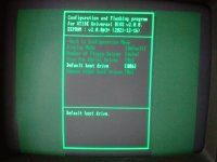
I saw that the default hard drive is 80h. I did not change it.
IMG_20220408_103659480.jpg

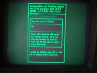
The scan for serial drives was off. I turned it on.
IMG_20220408_103752132.jpg

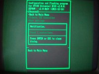
At some point I noticed it said it saw 1 controller.
IMG_20220408_103812803.jpg

I changed the display mode from color 80 columns to monochrome 80 columns. I think that just made the XTIDE BIOS announcement black on the black screen, though, so I changed it back to color 80 columns.
IMG_20220408_103925324.jpgIMG_20220408_104621874.jpg

IMG_20220408_104001108.jpg

I will try it on the Epson Apex 1 in the next few hours and report back on that.
 
For over 2 months the Compaq Portable 1 has been open on my kitchen table. I am resisting the urge to put its case back together immediately and move on immediately to the next project, but I need to properly end this project before moving on. The thing is, opening the Portable 1 case takes special tools used on plastic tabs. It is not at all as easy, simple, or repeatable to open as an IBM AT; in fact, if you didn't already have instructions on how to open the case, you would certainly break it by trying. So when I close the Portable 1 case soon, it must have everything in it placed and set as I want it to be, and I don't want to have to open the case again, almost ever. Because this XTIDE board will be permanent in the Portable 1 once I close the case, I've just ordered another kit that I can use in the Apex 1 or move to another computer. Hopefully, I now know enough that I won't have to spend 2 months to get it working.

I put my additional parallel-serial expansion board back in the Compaq Portable 1, and it still boots fine with the XTIDE board and the 256 MB. CF card.

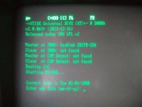
I tried the XTIDE in the Epson Apex 1 and it worked there as well with the 256 MB. CF card. It recognizes the 512 MB. CF card too, but won't boot from it. It says it is booting from C, but never progresses further.
IMG_20220408_163314351.jpg

Here are the items I still have to finish to close the Portable 1 project.
  1. Is the back-and-white/color setting the reason why the XTIDE BIOS announcement didn't show on the Portable 1? Setting it as color works, except that I can't see the legends beside the key names (A, C, F6, F8) on the top row.
  2. Both the Portable 1 and the Apex 1 boot fine with the XTIDE board and the 256 MB. CF card. Neither of them boot with the XTIDE board and the 512 MB. CF card; in that case, the XTIDE BIOS says it is booting from drive C and never proceeds. What do you think made the XTIDE board finally recognize the CF cards?
  3. The 512 MB. card is already formatted for DOS and is bootable in DOS 6.22. What can I do do make XTIDE recognize the 512 MB. card?
  4. Pressing A at the XTIDE BIOS screen queues the BIOS to boot using drive A. Likewise for the letter C. What do the F6 ("ComDtct") and F8 ("RomBoot") keys for in the XTIDE BIOS screen?
  5. Can I set the XTIDE BIOS to always try to boot from A first, and if not successful, try C?
  6. If I chose to put drives on the COM port(s), how would I do that?
 
What do you think made the XTIDE board finally recognize the CF cards?

You had three symptoms:
1. XUB not displaying the model information of the attached CF card.
2. The 'Auto Configure' functionality of XTIDECFG reporting "Found 0 controllers."
3. Cannot boot from A: if the XT-CF-Lite's EEPROM is enabled.

Symptom #1

Earlier, in experimentation, I disabled /CS1 by disconnecting pin 6 of U4 (i.e. /CS1 could then ever be asserted). But that did not show symptom #1. But just now, I simulated the 'pin 1 of U5' soldering problem you had - I instead disconnected pin 1 of U5. That showed symptom #1. That explains why initially (kit [including pre-populated EEPROM] just built, but pin 1 of U5 unsoldered), the symptom was seen.

Later, you soldered pin 1 of U5, but symptom #1 was still seen. But at that point, something else was causing the symptom: You had upgraded the XUB to release R622, and your attempts to use the 'Auto Configure' functionality of XTIDECFG resulted in "Found 0 controllers." (symptom #2). It turns out that when that happens, the XTIDECFG in R5622 sets the 'Device type' setting in the XUB to one of the "16-bit" values, which doesn't work for the XT-CF-Lite.

Symptom #2

Again, caused by the 'pin 1 of U5' soldering problem. Proved it myself on my XT-CF-Lite by disconnecting pin 1 of U5.

Symptom #3

Your "Pressing A at the XTIDE BIOS screen queues the BIOS to boot using drive A." implies that the symptom has gone.
 
It recognizes the 512 MB. CF card too, but won't boot from it. It says it is booting from C, but never progresses further.
The 512 MB. card is already formatted for DOS and is bootable in DOS 6.22. What can I do do make XTIDE recognize (sic) the 512 MB. card?
Try partitioning and formatting the card when it is on the XT-CF-Lite.
 
Actually, I realized there are 3 different color modes: color, black and white, and monochrome. I switched it to black and white and now the legend highlights show up on the Compaq 1. Good.

I also learned by failing to boot that on the Apex 1, I/O address 300h is occupied by the 25-pin serial I/O board I want to be present in it, so after I assemble the second XTIDE board intended for the Apex 1, I will have to set its switch 1 to something else.
Via XTIDECFG, set the 'Default boot drive' setting to 0.

Navigation: {Configure XTIDE Universal BIOS} {Boot settings} {Default boot drive}
It worked.
Try partitioning and formatting the card when it is on the XT-CF-Lite.
It did not work. I had to format it on the Apex 1 because the Portable 1 doesn’t have enough memory to run FORMAT in DOS 6.22, only 255 kB. total memory. The 512 MB. card, even once reformatted by the Apex 1, cannot be booted from by either the Portable 1 or the Apex 1.
Maybe the problem is the first one listed at [here].
 
Back
Top