• Please review our updated Terms and Rules here

Gotek / FF on Model 3

behines

Member
Joined
Feb 24, 2024
Messages
38
Location
Pasadena, CA, USA
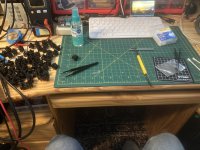
My diskless system upgrade is proceeding well. I very much appreciate the help I've received from the forum so far.

I am now thoroughly stumped by the Gotek however. I've scoured every site I can think of looking for info, including the post and video by mbliss and the Github site by GiveMeStrength, but I haven't achieved success yet after two days of trying.

First, the symptom I am seeing:
  • I turn the knob until it shows an image I want to boot from, then hit the red button
    • I've also tried press-clicking the knob after selecting, seems to have no effect.
  • The green LED comes on for a few seconds, but the track counter never changes
  • I have installed a 3V piezo across the JB pin pair as per this link, and no sound comes out.
  • After a few seconds (but before the LED goes out), I get the "Cass?" prompt.
This is a new Gotek, with the Artery AT32F435RGT7 chip.

And here's what I've done to get here:
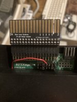
  • Set up the Gotek with jumper on S0 (moved from S1).
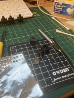
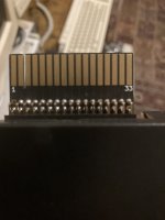
  • I left the J5-JA jumper in place as it came from the factory. It seems like this is an "idle" position just for parking the jumper? Below is a photo of how it came from the factory.
    • (I also tried jumpering JA, which one post indicated would generate a READY signal on pin 34. That turned the device into a brick that just froze at "Flashfloppy+ 3.38" - even though I have updated to 3.42. Moving the jumper back restored functionality.)
  • Connected it to the end of my floppy cable. (I've tried the other connector as well; in that case I get no green LED.)
  • I flashed to FlashFloppy 3.42. (It came from the factory with Flashfloppy+ 3.38.)
  • I configured FF.CFG with
    • interface = shugart (also have tried interface=jc)
    • host = unspecified
    • display-type = oled-128x64-rotate (this was necessary after the update to 3.42, wasn't needed with 3.38 factory firmware)
    • other values left at defaults
  • I used the HxCFloppyEmulator Windows app to create HFE files from .DSK files that I have found online
Factory jumper settings:
1710911064113.png


I'm stumped. Is it possible that I don't yet have a good image to boot from? I see that the original drives were 40 tracks but many of the DSK images I've found are 80 tracks.

I also have tried creating my own DSK by using HxCFloppyEmulator to export the disk's contents and then rebuild it as a JV1 or JV3 image, which I then export to HFE.


I will note that since this is a diskless-to-disk upgrade, unfortunately I have three things at once that are new:
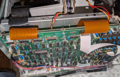
  • Floppy controller
  • Gotek
  • "Boot disk"
It feels like this is just a software problem. Is there a specific .DSK file that someone can refer me to, that is known to boot a Model III from a Gotek?

But is there anything in what I'm reporting that could indicate a problem with the floppy controller or my connection to it?

Should I try HxCFloppyEmulator instead of FlashFloppy?

Thanks,
Brad
 
Last edited:
I have one working in a Model 4. This picture shows my jumper settings. I am using FlashFloppy 3.42.

FF.CFG:
interface=jc, host=unspecified, display-type=auto.
pin2 = auto, pin34 = auto (Probably defaults).

Yes I would try a 40 track single density single sided image to start with.

IMG20240320175227.jpg
 
I have one working in a Model 4. This picture shows my jumper settings. I am using FlashFloppy 3.42.

FF.CFG:
interface=jc, host=unspecified, display-type=auto.
pin2 = auto, pin34 = auto (Probably defaults).

Yes I would try a 40 track single density single sided image to start with.

View attachment 1275993
Thanks for the super fast reply. This is basically what I'm doing but I will try your recipe verbatim.

Where would I get an image like you describe? I have tried following the process described here of essentially starting with a blank JV3 image and pushing files into it, but I'm wondering if that leaves me missing the boot block? This post indicates that Drive 0, Track 0, Sector 0 holds the bootstrap code. The behavior I'm seeing is what you might expect from inserting a non-bootable disk into the drive.

I feel like my file-by-file copy isn't going to write a boot block - that it's hard to "roll your own" bootable disk image. In which case I need to find one like you describe.

Am I thinking about this the right way?
 
Try the images in the post Kool65 listed above. My ff config along with some bootable disk images is included in that thread. Give those a shot and see if you get any life from it.

On a side note I had to repair my keyboard again. I ended up using vent tape and a punch to replace the carbon that had aged off in each switch. Hoping this will be a lasting fix I do not want to open it up again haha
 

Attachments

  • IMG_4122.jpeg
    IMG_4122.jpeg
    3.4 MB · Views: 3
  • IMG_4123.jpeg
    IMG_4123.jpeg
    1.9 MB · Views: 3
Wow, thanks again for the super fast response. I have set my jumpers and FF.CFG to match yours exactly, and I have put all those images on my USB stick.

Still no luck. I'm starting to think it's a cabling problem. I verified that my piezo speaker is working by enabling notification sounds at the bottom of FF.CFG. I hear it chirp and beep as I interact with the device. But the boot process is the same. Green light, then "Cass?"

I did notice one thing that made me think I was onto something briefly. The 34-pin IDC-to-edge connector adapter that I am using is something I pulled from my bin of ancient parts. When I looked at the bottom of it, I noticed that only pins 1 and 33 actually have gold fingers, and that they are tied together! But then I looked in the Tech Ref and it says that all odd-numbered pins are GND. So it seems like that's not it. Probably would be a little better to have a fully populated adapter, but I can't see that mattering.

I think my next act will be to inspect the cabling, particularly my new 20-pin connector cables that I mentioned before.

Thanks for all the help.

Brad
Try the images in the post Kool65 listed above. My ff config along with some bootable disk images is included in that thread. Give those a shot and see if you get any life from it.

On a side note I had to repair my keyboard again. I ended up using vent tape and a punch to replace the carbon that had aged off in each switch. Hoping this will be a lasting fix I do not want to open it up again haha
That's a clever fix!

I recently bought one of these conductive-ink pens to fix an aging contact in one of my thermostats, and also some damaged traces in a TI-99/4A keyboard. Seems to have worked so far. I like the simplicity of your approach.


I'll try out those images and CFG files this evening, thanks.
 

Attachments

  • 1710921870923.png
    1710921870923.png
    2.2 MB · Views: 3
Wow, thanks again for the super fast response. I have set my jumpers and FF.CFG to match yours exactly, and I have put all those images on my USB stick.

Still no luck. I'm starting to think it's a cabling problem. I verified that my piezo speaker is working by enabling notification sounds at the bottom of FF.CFG. I hear it chirp and beep as I interact with the device. But the boot process is the same. Green light, then "Cass?"

I did notice one thing that made me think I was onto something briefly. The 34-pin IDC-to-edge connector adapter that I am using is something I pulled from my bin of ancient parts. When I looked at the bottom of it, I noticed that only pins 1 and 33 actually have gold fingers, and that they are tied together! But then I looked in the Tech Ref and it says that all odd-numbered pins are GND. So it seems like that's not it. Probably would be a little better to have a fully populated adapter, but I can't see that mattering.

I think my next act will be to inspect the cabling, particularly my new 20-pin connector cables that I mentioned before.

Thanks for all the help.

Brad


That's a clever fix!

I recently bought one of these conductive-ink pens to fix an aging contact in one of my thermostats, and also some damaged traces in a TI-99/4A keyboard. Seems to have worked so far. I like the simplicity of your approach.


I'll try out those images and CFG files this evening, thanks.
I can’t take credit for that someone online came up with the idea. I can’t find the YouTube video at the moment but seems to be working so far. Model 3 keyboards are a pain.

I can’t remember where I got my edge connector adapters but they worked great for me. Definitely check out cabling. Keep us posted!
 

Attachments

  • IMG_4168.jpeg
    IMG_4168.jpeg
    2 MB · Views: 7
  • IMG_4169.jpeg
    IMG_4169.jpeg
    1.8 MB · Views: 6
Victory!!

It was a cabling problem. I gently lifted out the motherboard and flipped it on its back without disconnecting the orange flex cable connectors, and when I rung out the cable, fully 3 of the 20 pins were not connected.

The problem is the connector at the motherboard end. It is truly horrid. I couldn't get the wooden pencil trick to work, and my credit card trick wouldn't work because the credit card has to come in from the side of the connector that is covered by the cable. (It only works if you connect to the motherboard first, then to the controller.)

I finally was able to coerce all the contacts into place with a credit card though. Even then, 0.1" apparently isn't quite the same in China as in the 1980 US, and I had to take a fair bit of care to make sure all the contacts were aligned.

In hindsight, I will say that I think it would have been better to do violence to the board and desolder the old connectors and swtich to a SIP header. These motherboard connectors are really barely usable.


Eventually though, they all went into place, and I plugged in the TRSDOS image you provided, and WOO HOO IT WORKED.

Thanks everyone for all the help. It was your help and advice that convinced me that the problem must be in hardware, and now I'm up and running.

And, in the extra good news dept, PCBWay finished fab of my FreHD today and it will be on its way soon.
 
Last edited:
Victory!!

It was a cabling problem. I gently lifted out the motherboard and flipped it on its back without disconnecting the orange flex cable connectors, and when I rung out the cable, fully 3 of the 20 pins were not connected.

The problem is the connector at the motherboard end. It is truly horrid. I couldn't get the wooden pencil trick to work, and my credit card trick wouldn't work because the credit card has to come in from the side of the connector that is covered by the cable. (It only works if you connect to the motherboard first, then to the controller.)

I finally was able to coerce all the contacts into place with a credit card though. Even then, 0.1" apparently isn't quite the same in China as in the 1980 US, and I had to take a fair bit of care to make sure all the contacts were aligned.

In hindsight, I will say that I think it would have been better to do violence to the board and desolder the old connectors and swtich to a SIP header. These motherboard connectors are really barely usable.


Eventually though, they all went into place, and I plugged in the TRSDOS image you provided, and WOO HOO IT WORKED.

Thanks everyone for all the help. It was your help and advice that convinced me that the problem must be in hardware, and now I'm up and running.

And, in the extra good news dept, PCBWay finished fab of my FreHD today and it will be on its way soon.
Heck yea! Great job! Persistence and patience pays off :)
 
Back
Top