I'm restoring this computer and have no horizontal or vertical output signals on the 6845 CRT controller (pin 39 and pin 40). The chip has been replaced, and all the DC voltages are there, and the ground is good. I get a clock signal to pin 21. My question is what other signals are needed to make this chip operate correctly. The horizontal and vertical signals were working at one time but just stopped. Any help would be appreciated. Thanks.
- VCF South West - June 14 - 16, Davidson-Gundy Alumni Center at University of Texas at Dallas
- VCF West - Aug 2 - 3, Computer History Museum, Mountain View, CA
- VCF Midwest - Sept 7 - 8 2024, Schaumburg, IL
- VCF SoCal - Mid February 2025, Location TBD, Southern CA
- VCF East - April 2025, Infoage Museum, Wall NJ
-
Please review our updated Terms and Rules here
You are using an out of date browser. It may not display this or other websites correctly.
You should upgrade or use an alternative browser.
You should upgrade or use an alternative browser.
Heathkit H89A Question
- Thread starter JimboX
- Start date
ldkraemer
Veteran Member
Do you have the following:
1. CCLK Signal pin Pin 21 of the 6845?
2. /CS on Pin 25 (Low)
3. R/W (Low = WRITE) on Pin 22
4. /RST on Pin 2 (LOW = RESET)
Larry
1. CCLK Signal pin Pin 21 of the 6845?
2. /CS on Pin 25 (Low)
3. R/W (Low = WRITE) on Pin 22
4. /RST on Pin 2 (LOW = RESET)
Larry
Thank you, Larry, for your quick reply. I get a good clock signal at pin 21, but on pin 2, 22, and 25, I get nothing. At one time I got the high voltage and a raster on the screen. Now nothing. It just stopped working. Thanks for any help you can give me.
ldkraemer
Veteran Member
JimboX,
When you man nothing, are you getting a LOW (anything less than +.8 VDC) or
HIGH (Anything Greater than about +2.7 VDC). There can be one other option
and that is +.7 VDC. I've fount Signals that feed IC's with INPUT Pins that are
stuck at +.7 VDC, and that isn't a good thing.
I downloaded the Schematics for Heath H89A. What CPU is used? I'd like to
look at what is feeding the /CS to the 6845 and other interface Signals. I've been
through something similar with a Kaypro 4 chasing signals and verifying the Vertical
and Horizontal Sync signals.
Pin 2 /REST should be +5 VDC. If it is always LOW ( <.8 Volts) you need to see
why VCC1 isn't high.
Larry
Last edited:
ldkraemer
Veteran Member
Pin 2 should be /RESET. I had a typo.
Larry
Larry
mgarlanger
Experienced Member
Hey JimboX,
You should check out/join the sebhc mailing list - https://groups.google.com/g/sebhc lots of great info, and hardware experts on the H89. (and I'm not just saying it because I manage the list )
)
You should check out/join the sebhc mailing list - https://groups.google.com/g/sebhc lots of great info, and hardware experts on the H89. (and I'm not just saying it because I manage the list
)Dwight Elvey
Veteran Member
It might be a problem with the microprocessor and not the controller. There is a way, to boot from a serial terminal. It might be better if it does boot so that you can use the H89's monitor code to talk to the controller.
Dwight
Dwight
daver2
10k Member
Yes, the 6845 requires programming correctly before it will generate anything. If the 6845 is programmed incorrectly (due to a faulty data bit or ROMROT) then it may either not generate anything, or it may generate strange waveforms...
You need to see if there is any activity on the 6845 /CS pin (following a reset).
After that, you will need a logic analyser to log the actual data writes to the 6845 to see if they make sense.
Dave
You need to see if there is any activity on the 6845 /CS pin (following a reset).
After that, you will need a logic analyser to log the actual data writes to the 6845 to see if they make sense.
Dave
I'll do that. You're doing a great job as far as I can see.Hey JimboX,
You should check out/join the sebhc mailing list - https://groups.google.com/g/sebhc lots of great info, and hardware experts on the H89. (and I'm not just saying it because I manage the list
I'm back. I'll check out pin 2 and see if there's any activity on it. I'm not sure what a logic analyzer is or how to use it if it becomes necessary to do so. Thanks.Yes, the 6845 requires programming correctly before it will generate anything. If the 6845 is programmed incorrectly (due to a faulty data bit or ROMROT) then it may either not generate anything, or it may generate strange waveforms...
You need to see if there is any activity on the 6845 /CS pin (following a reset).
After that, you will need a logic analyser to log the actual data writes to the 6845 to see if they make sense.
Dave
ldkraemer
Veteran Member
daver2
10k Member
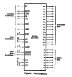
It is also worth looking at /M1, /MREQ and /IORQ to see if the CPU is even doing anything.
Dave
Dave
jlang
Experienced Member
A handy was to check if the processor is running properly is to put the terminal in local mode and press ctrl G (bell)
if it's mostly running it should make a noise.
if it's mostly running it should make a noise.
Hope this helps some what.Do you have the following:
1. CCLK Signal pin Pin 21 of the 6845? Yes.2.54 volts
2. /CS on Pin 25 (Low) No signal. 3.89 Volts
3. R/W (Low = WRITE) on Pin 22 No signal 3.83 volts
4. /RST on Pin 2 (LOW = RESET) No signal 5 volts
Larry
I do get a clock signal into pin 6 of the CPU.JimboX,
One other thing you can Check is the Control Inputs to the Z80 CPU, Something may be making
one of the Control Inputs LOW causing the CPU to wait.
Pin 16 - /INT No Signal 0 volts.
Pin 17 - /NMI No signal 4.5 volts
Pin 24 - /WAIT No signal 5 volts
Pin 26 - /RESET No signal 5 volts
Larry
I'll check this out and get back to you.It is also worth looking at /M1, /MREQ and /IORQ to see if the CPU is even doing anything.
Dave
I do get a clock signal into pin 6 of the CPU.
I'll check this out and get back to you. Thanks for all the help. I really appreciate it.
I'll do that. Did you see the results from the CPU and the CRT controller?It is also worth looking at /M1, /MREQ and /IORQ to see if the CPU is even doing anything.
Dave
daver2
10k Member
No I didn't...
/INT is not correct at 0V. That implies a standing interrupt from a device.
Also, you have not 'proven' the /RESET signal yet. This signal should normally be +5V. But this signal should be held briefly at 0V on a reset.
It should be possible to manually generate a reset pulse by shorting out capacitor C507 (in the reset circuit) with a low-valued resistor. This should pull the /RESET line LOW.
Dave
Last edited:
Thanks, Dave. This gives me something to shoot for. I'll try to generate a reset pulse like you said. I'll also work on the INT/ problem. I'll let you know what I find out.No I didn't...
/INT is not correct at 0V. That implies a standing interrupt from a device.
Also, you have not 'proven' the /RESET signal yet. This signal should normally be +5V. But this signal should be held briefly at 0V on a reset.
It should be possible to manually generate a reset pulse by shorting out capacitor C507 (in the reset circuit) with a low-valued resistor. This should pull the /RESET line LOW.
Dave