timleach
Member
Hi everyone! I’ve recently come into possession of a Commodore PET 4016, in quite good condition, and I’d really like to see if I can get it working.

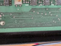
PXL_20240713_2027286751920×2550 353 KB
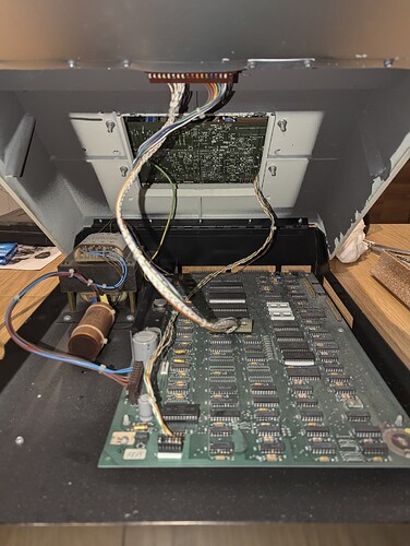
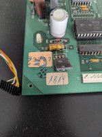
PXL_20240713_2203136021920×2550 340 KB

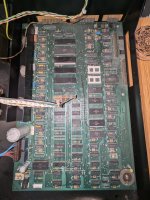
PXL_20240713_2203333941920×1446 259 KB
Problem is, I don’t really know what I’m doing! I’ve never done this kind of maintenance before. I studied electronics in school, so I know how to use a multimeter and a soldering iron, and I know the difference between resistors and transistors and capacitors and stuff, but I’m completely at a loss when it comes to diagnosing problems with a big complicated system like this.
So, I’d really appreciate some help trying to get this lovely machine working again. I’ve tried to read guides online, but they use language I’m unfamiliar with and skip out large steps that I need.
Here’s what I’ve done so far:
So, those voltages don’t seem right, but I don’t really know what to do about that. If the power supply is faulty, can I get by somehow by using a replacement modern power supply that provides +12V, +5V, 0V and -5V, or would I have to somehow track down a replacement?
Sorry for the long read, I hope this is of interest to the people here! I look forward to any guidance you all have for me


PXL_20240713_2027286751920×2550 353 KB

PXL_20240713_2203136021920×2550 340 KB

PXL_20240713_2203333941920×1446 259 KB
Problem is, I don’t really know what I’m doing! I’ve never done this kind of maintenance before. I studied electronics in school, so I know how to use a multimeter and a soldering iron, and I know the difference between resistors and transistors and capacitors and stuff, but I’m completely at a loss when it comes to diagnosing problems with a big complicated system like this.
So, I’d really appreciate some help trying to get this lovely machine working again. I’ve tried to read guides online, but they use language I’m unfamiliar with and skip out large steps that I need.
Here’s what I’ve done so far:
- Visual inspection: looks good, inside and out
- Plug it in and turn it on: nothing, not even a piezo beep. Occasionally (about 50% of the time) when I turn it on I hear a quiet “thunk” from the power supply area, but that’s the only different thing that happens
- Check fuse: fuse is intact and conducting
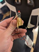
- Check voltages coming out of power supply: now here’s the weird part.
- red = +5V
- blue = -5V
- brown = +12V
- Pin 4 (brown): -0.05V
- Pin 6 (brown): -0.05V
- Pin 7 (blue): +7.13V (why is it not negative?)
- Pin 8 (blue): +7.46V
- Pin 9 (brown): +9.65V
- Pin 10 isn’t connected to anything, so I don’t want to connect my multimeter to it directly (maybe this isn’t a concern, but I’m playing it safe)
- Pin 11 (brown): fluctuates around +10V
So, those voltages don’t seem right, but I don’t really know what to do about that. If the power supply is faulty, can I get by somehow by using a replacement modern power supply that provides +12V, +5V, 0V and -5V, or would I have to somehow track down a replacement?
Sorry for the long read, I hope this is of interest to the people here! I look forward to any guidance you all have for me


