• Please review our updated Terms and Rules here

Help with TEI floppy controller

Endersending

Experienced Member
Joined
Mar 14, 2023
Messages
119
Location
Walker, Minnesota
Hello to everyone,
I have an IMSAI 8080 I am currently working on. recently purchased a floppy controller and a serial card from ebay and now that I have them with no documentation I am stuck.
The floppy controller:
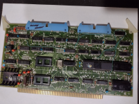
teifloppy.png
This is a TEI inc FDC-2 floppy controller card. I have been looking for a manual or documentation or anything else but my searching is coming up short.
Deramp.com has a picture (which I believe is this actual card, since they both have the pen writing on the left blue cable connector) and also a picture of the schematics which is too low resolution to read. If anyone has any information about this card I would greatly appreciate it.
The card uses a FD1771 controller for the floppy. I would think the design of the board is generic except for jumpers/configuring. To the left of the upper eprom socket, there are some solder points on the board labeled "port" and H, L, B. What is a port to a floppy controller? I think H = high, L = low, B = bit. So you would solder a jumper from B to either H or L depending on what you want the bit set to. The board currently shows the rght most bit jumped low and the rest floating. I think.
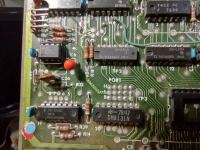
portjmp.png
There is also another jumper between the blue cable connectors. 2 rows, one marked SK K and SD D. I am thinking the SD D is for single or double density? maybe not.
There is also a jumper block above the crystal in the middle of the board. the left of the jumpers say B L H (bit, low, high?) and numbers going across 2, 14, 4, 12, 6, 10. Maybe these are address bits? you can see from the picture below that the jumpers have default settings: 010111
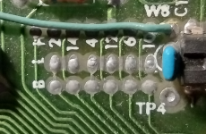
addressjmp.png
The 2 empty sockets on the board are for EPROMs. when I purchased the board the picture on ebay showed a 2708 EPROM chip in the lower socket with a label on it saying "F000, V1.43". That chip did not come with the board and the seller has no idea where it is.
I assume F000 is the address of the chip, and so I could also assume that I could put a new chip in that socket, I could access it at that address. does this sound correct? I am also thinking that the EPROMs are separate from the floppy controller, in that they do not need each other to function.
This leaves me at the next step of creating a bootable rom image. What would be a good image to start with? I know there are some different monitors people have written over the years and I would have to modify code to match my setup. Like addresses to where the floppy controller lives, and where the serial card is addressed.
Any help, information and insight into how this card operates would be extremely helpful. I also bought a serial card with the same problem of not having documentation or knowledge to use it and I will post that in a different thread.
Thank you for the help. It is awesome to to have resources like this to ask questions.
 
2, 4, 6, 10, 12 and 14 suggest to me as octal numbers.

The ROM should be in memory space (starting at F000) and the FDC will be in I/O space.

You should be able to identify the FDC controller ports by writing a test program. Write to an I/O port and read back from it to see if it returns the same data as was written. If so, print out the I/O address. Do this with the controller card removed and then with it in.

The FDC will contain a track and sector register that should read back what is written to them.

There will likely be some other I/O ports that are used to select the disk drive, density etc.

I would look at the Cromemco 4FDC and 16FDC. These cards have a monitor included. I have stripped this down to a bare minimum for another job.

You could also put a logic probe or oscilloscope on the FDC controller chip select pin and manually read from I/O ports to see at what point the logic probe or oscilloscope triggers. This will indicate the I/O ports that are being used.

A bit of testing is fortold in your future...

Dave
 
Trying to get this board running with no documentation is going to be a very formidable project. TEI's S100 board products were not widely used therefore as you have already discovered little documentation exists. Even Herb Johnson's retrotechnology.com web site (which often has documentation on S100 systems not available anywhere else) lists no documentation for this board. While the FD1771 was a commonly used floppy controller chip in vintage S100 systems, virtually every manufacturer implemented things differently. You could face having to figure out not only how to control this board, but also having to write all the floppy software from the ground up.

Unless you plan to spend months of work on this project alone, perhaps we can suggest alternate solutions that would allow you to get a floppy based system up and running on your IMSAI much faster. Just waiting until you can get a Cromemco floppy controller on eBay (they come up for sale fairly often) would be a far better option since there is a lot of documentation and software available.
 
Last edited:
Unless you plan to spend months of work on this project alone, perhaps we can suggest alternate solutions that would allow you to get a floppy based system up and running on your IMSAI much faster. Just waiting until you can get a Cromemco floppy controller on eBay (they come up for sale fairly often) would be a far better option since there is a lot of documentation and software available.

This is one reason I warmed to the S-100 Northstar double density floppy controller was that it is "Plug & Play" All the coding it needs is in the OTP Proms on its board (I cloned those too as spares). To make it run in a SOL-20 one just types EX E800, and off it goes with the CP/M disk in the drive.

I hate it when documentation is missing. The N* controller is well documented, the manual is on the net and I was able to buy the original manual too.

The lengths I have gone to in the past to acquire documentation for old computer cards is extreme, even finding some in Museums.

I used two 5.25" floppy drives in a case with Mike Douglas's VSG, so I can use soft sector floppies. It runs Lifeboat Associates's CP/M 2.2 very well with no problems. I Also tried the Northstar DOS, but I prefer the CP/M.

I cannot recommend Mike's VSG highly enough. I put mine in the enclosure with the two drive units:

www.worldphaco.com/uploads/EXTERNAL_DUAL_5.pdf

If the OP gets really stuck, I think I have a spare N* double density S-100 card I could sell, in my stuff, I would have to check.
 
........PS: I also found a double density N* card that had been configured for an address of D000 or similar, the label was on the OTP PROM. I kept it because I realized that if I inspected the bytes in the Prom, and compared that to the OTP Prom, from the standard one that executes at E800, I would likely be able to figure out how to change the bytes to make an N* card operate at any address (even though I did not understand the coding going on in the first place)

Also, one thing that surprises me about the N* double density card, which seems so easy and problem free to use (for me at least), and the general interest in S-100 computers, is that somebody has not made an exact clone of it yet. An exact clone is a fairly easy task with the dual sided pcb and all the IC's and other parts on it are readily available. The original MDS boards seems to be getting a tad rarer, and they don't come up on ebay as much as they once did. Though the less desirable single density cards appear more commonly.

This is the N* double density card:

 
Last edited:
Figuring out the base port of the FDC chip and EPROM address is just one of many puzzles you'll be in store for. Most controllers had some form of read sync circuitry that used either CPU halt, wait states, DMA, FIFOs, or other mechanisms to allow sector data reads using CPUs that were too slow to monitor DRQ and then read, store, increment, check for done, and loop within the byte rate interval. Drive select, side select, and sometimes write precompensation were not standardized for the 1771 based designs, either. Interrupt handling and acknowledge are also going to be implementation dependent.

I hope you can find documentation. I share your situation as I'm in the same boat with a couple of boards myself.
 
N* documentation is plentiful. No problem there...

Hugo's question was related to the memory decode PROM - which is straightforward to reverse engineer. It is just a PROM with inputs and outputs that are known - as are the associated addresses.

You wouldn't happen to be thinking of old revision Cromemco cards would you... I will have a look at my stash of Cromemco documents for you.

Dave
 
Sorry, new to posting here so hadn't figured out the context conventions yet. I was commenting about the original post and the TEI controller. Trying to figure out an undocumented FDC design when a large fraction of the functionality is implemented external to the LSI chip is not an easy task. I agree getting a Northstar or other well documented card would be a more successful path forward.

@daver2 yes the card I have that needs documents is the Cromemco 64KZ-II (legend rev B) for which I created a separate post. Thank you for the offer to look through your documents.
 
I have learned alot about s-100 computers and floppy controllers in the last few weeks. I have decided to abort the TEI controller since I do not have the knowledge right now to make it work. I will put it on ebay and maybe someone else wants to tackle it. I purchased a Cromemco 4FDC that has a built in serial port and a eeprom with rdos 1 on it. I will post my adventure with that in another thread.
The case that Hugo Holden created for his floppy drives is amazing. I wish I had the skill to create something that beautiful.

Thank you everyone for the help.
 
The case that Hugo Holden created for his floppy drives is amazing. I wish I had the skill to create something that beautiful.

Thank you everyone for the help.

The good news is that Takachi in Japan, which you can easily communicate with via the email on their website, are super helpful.

The fellow in the in mail order division is Jelvin Lim.

If you give them the dimensional diagrams, their CNC department will cut the panels for you before they send the housing. (at a very reasonable price). They are used to sending things all over the World and being paid by Paypal.

They can also make non-standard sized housings too.

They did not have a housing suited to a VDU case I needed, but somehow they quickly re-tooled to make these for me. They are like the ones I used for the disk drives, but wider. I wanted these to re-house some IBM5155 VDU's


The quality of the finish on their housings is wonderful and highly scratch resistant. And the precision of the extruded metalwork is amazing. This sort of thing is somewhat typical of the uncompromising nature of Japanese electronics & mechanical engineering and the pride they have in their work.

(The only place I have felt safe to go on a Roller Coaster is in Japan. Because they way they do it, the chances of mechanical failure is near zero. Also you see a lot of small extra touches on their machinery, for example, on the roller coaster, somebody had used an Artist's brush with a fine stripe of yellow paint on all the nuts/threads and bolt heads, so they could quickly see if any of them had rotated and everything is in immaculate order. Even the average sandwich in a store looks like it has been wrapped by an Origami expert)
 
Back
Top