MykeLawson
Experienced Member
- Joined
- Mar 21, 2014
- Messages
- 387
Since my S-100 will only have boards, besides the CPU Board (https://forum.vcfed.org/index.php?threads/homebrew-s100-cpu-board.1245502/), I noticed something that may be an issue. The I/O Board uses a couple 74LS138s for port decoding, and the port decode for the two 8251A serial chips go straight to the /CS pins. This would mean that any address put on the bus that has the values associated with those two devices would cause the 8251A's to be selected. That would probably not be an issue since the IO Read and IO Write signals would not be active. However, out of the abundance of caution, I took the /IOREQ signal from the Z-80 on the CPU and connected it to an used S-100 bus pin. That signal could be used on the I/O Board to prevent either 8251A to be selected unless an IO operation is occurring. I may, or may not implement this.
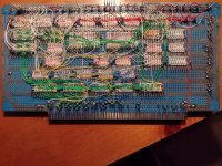
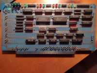
The I/O Board contains two serial ports, one for the system console, and one for transferring data to & from an external source (my PS/2 File Server), a parallel printer port (identical to the printer card on my STD bus machine), and a parallel ASCII keyboard (modified from the Osborne keyboard kit another user here posted).
The I/O Board contains two serial ports, one for the system console, and one for transferring data to & from an external source (my PS/2 File Server), a parallel printer port (identical to the printer card on my STD bus machine), and a parallel ASCII keyboard (modified from the Osborne keyboard kit another user here posted).