sqpat
Experienced Member
Hey all, I think EGA is a subject most relevant to early PCs and clones so I thought it most appropriate to post here.
I have a IBM 5155 PC with the ATI EGA Wonder driving an EGA signal to the internal monitor. I wanted to have support for an external display without purchasing an expensive EGA monitor. I ended up building an EGA to VGA adapter. It wasn't very hard and I'm personally not great with electronics/hardware yet I was able to do it anyway.
Let me note there are "EGA to VGA" converters all over the place on ebay but my understanding is they don't actually work for 21.8khz EGA frequencies and are more meant for certain arcade cabinets.
In EGA to VGA conversion there are basically there are two problems to solve:
1. Horizontal frequency mismatch (EGA scans at 15.7 and 21.8, VGA is 31.4)
My circuit does not fix this part - However, I already owned a NEC MultiSync 1970NX, a somewhat cheap LCD monitor from the early 2000s. It's a standard vga/dvi monitor but does a good job of accepting a wide range of frequencies, such as the 15/24khz seen in Japanese retro PCs. Turns out, it also handles EGA's frequencies just fine! Please note that not every newer "multisync" branded monitor actually can support this. You can pick this model of monitor on ebay for under $40 shipped. You might even find one on your local craigslist.
2. TTL to Analog signal conversion
So this is what the circuit actually does! First, here are VGA/EGA pinout references:
EGA: http://what-when-how.com/wp-content/uploads/2012/06/tmp7ee1137.png
VGA: https://i.stack.imgur.com/DtrXl.gif
Here's a reference for the basic how to to convert the TTL signals to Analog: https://www.repairfaq.org/sam/vidconv.htm#nvctlvg
Another forum member, ejs suggested i use 1k and 470 ohm resistors as they are much more readily available, and it worked fine for me. Also, you can ignore the termination part as its not necessary as part of the circuit.
So really, you just link up the similarly named pins, and when it comes to RGB pins you handle each color as an individual case of the above referenced circuit - EGA 0/LSB pin to the 1k resistor and 1/MSB pin to the 470 ohm resistor, joining both into the VGA pin for that color.
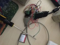
Here is an early example of the circuit. (Eventually I put it in a project box and used shorter wires to keep it neat.)

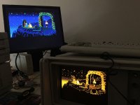
Here it is in action.

Well, it's not the greatest solution in the world, and from time to time I see some fuzziness. I imagine with a proper project board and more stable connections the quality would be better, but it suits my purposes.
Now, I have found that it doesn't work when I play CGA games. I've yet to determine the cause of this - lack of support on the ATI card, inability of the Multisync to handle the frequency, etc. But this really hasn't come up too often. If I find a solution I'll mention it here
I have a IBM 5155 PC with the ATI EGA Wonder driving an EGA signal to the internal monitor. I wanted to have support for an external display without purchasing an expensive EGA monitor. I ended up building an EGA to VGA adapter. It wasn't very hard and I'm personally not great with electronics/hardware yet I was able to do it anyway.
Let me note there are "EGA to VGA" converters all over the place on ebay but my understanding is they don't actually work for 21.8khz EGA frequencies and are more meant for certain arcade cabinets.
In EGA to VGA conversion there are basically there are two problems to solve:
1. Horizontal frequency mismatch (EGA scans at 15.7 and 21.8, VGA is 31.4)
My circuit does not fix this part - However, I already owned a NEC MultiSync 1970NX, a somewhat cheap LCD monitor from the early 2000s. It's a standard vga/dvi monitor but does a good job of accepting a wide range of frequencies, such as the 15/24khz seen in Japanese retro PCs. Turns out, it also handles EGA's frequencies just fine! Please note that not every newer "multisync" branded monitor actually can support this. You can pick this model of monitor on ebay for under $40 shipped. You might even find one on your local craigslist.
2. TTL to Analog signal conversion
So this is what the circuit actually does! First, here are VGA/EGA pinout references:
EGA: http://what-when-how.com/wp-content/uploads/2012/06/tmp7ee1137.png
VGA: https://i.stack.imgur.com/DtrXl.gif
Here's a reference for the basic how to to convert the TTL signals to Analog: https://www.repairfaq.org/sam/vidconv.htm#nvctlvg
Another forum member, ejs suggested i use 1k and 470 ohm resistors as they are much more readily available, and it worked fine for me. Also, you can ignore the termination part as its not necessary as part of the circuit.
So really, you just link up the similarly named pins, and when it comes to RGB pins you handle each color as an individual case of the above referenced circuit - EGA 0/LSB pin to the 1k resistor and 1/MSB pin to the 470 ohm resistor, joining both into the VGA pin for that color.
Here is an early example of the circuit. (Eventually I put it in a project box and used shorter wires to keep it neat.)

Here it is in action.

Well, it's not the greatest solution in the world, and from time to time I see some fuzziness. I imagine with a proper project board and more stable connections the quality would be better, but it suits my purposes.
Now, I have found that it doesn't work when I play CGA games. I've yet to determine the cause of this - lack of support on the ATI card, inability of the Multisync to handle the frequency, etc. But this really hasn't come up too often. If I find a solution I'll mention it here
Last edited:
