• Please review our updated Terms and Rules here

Honeywell 200 resurrection

Great news about the front panel. Now you just need a computer!

As I was looking over some of those photos, I noticed that all have only 4 bits/buttons for the control register. But according to H200 programmer's guide, the variant character for LCR was already supporting more than 16 registers (mostly expansion for peripheral channels). The core CPU CRs (64, 66, 67, 70, 76, 77) seem to be non-conflicting with peripherals channels, so with a small enough complement of peripheral channels one would get by with only 4 bits. But I wonder if these machines (with 4-bit CR entry) either had a smaller number of peripheral channels or else the customers just got by without access to the additional channel registers from the front panel?

P.S.: I guess the "console typewriter" on 220-2/3 consoles eliminates the front panel and any dependency on a specific number of buttons (in any field). So, perhaps "larger" machines were just always configured with 220-2/3 consoles, and didn't depend on any mechanical expansion of buttons.
 
Last edited:
Are you referring to peripheral channels or read/write channels? The former are each permanently connected to particular peripheral controllers, so more peripherals need more channels, but the latter connect any one peripheral to a buffer in memory just for the duration of one transfer operation. Therefore the read/write channels define how many simultaneous peripheral operations can occur. How many read/write channels can be accommodated depends on the speed of main memory as they are all time-sharing the memory. The smaller machines cater for four, medium machines eight and only the largest fastest can service sixteen, but these would have had much different architecture from the basic 201 processor. Faster peripherals could use more than one read/write channel in parallel to get access to more of the main memory cycles.

I can't think of a reason to be accessing read/write channel control registers within program code and it seems even more unlikely to want to do it from the control panel. Generally these registers were controlled solely by the peripheral controllers, not the CPU, once the CPU had initiated a transfer. The programmer's manual explained what was possible, not just what was useful in practice.

The machine would not enter stop mode until currently running peripheral operations had ended, so the control panel couldn't usefully display or enter values in these registers. Also the control panel had no way of displaying which peripheral had last been connected to which read/write channel and, when the machine was in stop mode so that the panel could be used, no peripheral was using any of them, so the read/write register contents were even more useless.
 
Last edited:
I guess I was talking about the read/write channels, specifically the things that are using CLCx and SLCx registers.

The reason I believed they were accessible from the front panel was for debugging. After a peripheral operation, which might end prematurely, being able to examine memory where the I/O took place would be useful. These registers contain the addresses - at least the address indicating where the operation started and ended. Similar to the BAR and AAR, they might be invaluable when trying to figure out what went wrong.

Even within a program one might need/want to access those registers, for example to compute the actual length of a tape record after reading. I haven't found definitive documentation to this effect, but I assume that the tape transfer ends when the record gap is encountered on the tape, so the program might need to check whether enough data was transferred. In the Unix world, one also needed to check for 0-length records which indicate EOF. I'm not sure if anyone used that convention on the H200 (I do see references to records that contain " EOF" for that purpose). While I haven't seen any reference to this capability in documentation, one could theoretically use these registers to handle variable-length records (on certain media). For that matter, input from the console typewriter might need that (from what I can tell, pressing return ends the input operation).
 
I don't think I've seen the H2000 manual but this reference is to use of the register values within a program where the relevant channel can be identified. Assuming that a large machine running many programs would be assigning channels dynamically one wouldn't know which channel to look at and also one would have to stop the whole machine. I would expect peripheral failures to be investigated by diagnostic programs rather than manual use of the control panel.

CPU registers can usefully be manipulated through the control panel but read/write registers pose a different problem.
 
Last edited:
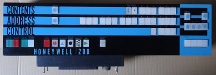
Regarding the photo of the front panel with 18 "Address" buttons, I wonder if this might also influence the number of buttons there:
1696282996030.png
i.e. if one had 48K core but added the Scientific Unit, did that warrant a front panel with 18 address buttons?
 
I don't think I've seen the H2000 manual but this reference is to use of the register values within a program where the relevant channel can be identified. Assuming that a large machine running many programs would be assigning channels dynamically one wouldn't know which channel to look at and also one would have to stop the whole machine. I would expect peripheral failures to be handled by diagnostic programs rather than manual use of the control panel.
I would have believed this was done under "controlled circumstances". In a "bare" program running on the machine, the program knows when the channel is re-used. In the case of things like OS/2000, the interrupt handler that "completes" the operation would grab these values before releasing the channel. Either way, typically these registers would be read right after the PDT instruction finished, before any other one was issued for the same channel. This is fairly common for operating system code.

FYI, I do see the same wording in the H200 manual, I just needed to find where to look (chapter 2).
 
You have clearly studied the low level programming of the larger machines that I never needed to as by the time we had these larger machines I had moved on to high level programming languages, then system design and finally business analysis and corporate data modelling where we specifically banned any references to the software systems and hardware the company was currently using. There was also a separate operations department that dealt with the practicalities of keeping the present machines working correctly.

We found that end users were becoming accustomed to thinking in terms of how the computer systems worked instead of the business, which meant that we system designers had to reverse engineer what they thought they wanted from the computers to work out what the business actually needed. It was hard working pulling the business users away from this topsy-turvy way of thinking. Equally hard work was converting their own in-department programs written by them without adequate supporting documentation when we had to make all our systems millennium bug proof. In many cases the people who wrote the programs had moved out of those departments and nobody knew exactly what the programs were supposed to do because no specifications had been written for them no matter how big and complicated they got. Within our department these appalling systems were given the name "E U Monsters" (E U being End Users). Anybody can write a computer program but not everybody can write a permanently maintainable one.

Also as we were a financial institution I'm not aware that any of our machines needed or had a scientific unit, "scientific" being the significant word there. In fact I have little interest in any machine with a fixed word length architecture. As personal computers have moved from 8 to 16 to 32 to 64 bit architecture I've found them progressively more boring.

My H200 project is actually a personal refuge from the mad race to build bigger and allegedly better, which is why restricting myself to building the most basic specification machine is not simply an attempt to make the job easier. I even made the main memory 8K instead of 4K only because the chap who gave me the 4K memory modules wanted me to include two, but even then I told him that I wouldn't necessarily build in three character address mode to access all of it. The minimum memory specification for an H200 was actually 2K but I don't think there were any 2K memory modules made even though the memory unit architecture supported their use.
 
...
We found that end users were becoming accustomed to thinking in terms of how the computer systems worked instead of the business, which meant that we system designers had to reverse engineer what they thought they wanted from the computers to work out what the business actually needed. It was hard working pulling the business users away from this topsy-turvy way of thinking. Equally hard work was converting their own in-department programs written by them without adequate supporting documentation when we had to make all our systems millennium bug proof. In many cases the people who wrote the programs had moved out of those departments and nobody knew exactly what the programs were supposed to do because no specifications had been written for them no matter how big and complicated they got. Within our department these appalling systems were given the name "E U Monsters" (E U being End Users). Anybody can write a computer program but not everybody can write a permanently maintainable one.
...
Yeah, this has been a familiar set of themes throughout my career, too. Especially getting users to tell me at a high level what they need, rather than what they think I'll do to implement it. I must admit that I have a hard time writing documentation, but I do recognize the value so I make an effort on occasion. Nothing bugs me more than trying to use (or repair) something that has no documentation. I guess "E U Monsters" is kinder than the "ID-ten-T" label... (id10t...)
 
While working for the Defense Mapping Agency back in the 80's, a condition of employment was that you were able to accomplish the task with little or no technical support or supervision, including manuals, spares, schematics, scripts, etc. Whether or not you possessed any programming experience was irrelevant, and you were left to your own resources to devise enough code to step a woebegone machine through it paces. Many phone calls and lots of research.
Nothing bugs me more than trying to use (or repair) something that has no documentation.
 
Moving on ... I think I've worked out how those one-shot buttons with the mysterious blue boxes function, having detected capacitance across the input terminals, inductance across the outputs, fine wires inside the boxes and the microswitch contacts being connected to both input terminals. I have also now traced the wiring to them inside the control panel which supports this analysis. It's evidently a pulse transformer circuit.

One-shot schematic.jpg
 
That makes sense. from your photo of the assembled panel with the back open, the "one-shot" buttons all represent functions that are strictly one-shot in nature - i.e. a "steady ON" would likely cause undesirable repetitions or other side-effects. Like the "DISPLAY+1" and "DISPLAY-1" buttons - it would be infuriating if one kept getting multiple "+1" or "-1" actions from a single press of the button. But the "DISPLAY" button would not suffer from that and so it does not have the one-shot module.
 
Actually I thought it was a belt and braces approach (is that idiom too English?) as the logic circuits to which these switches are attached (Now that grammar is just English pedantry but I enjoy using it.) all appear to have their own lockout mechanisms to stop repetitions anyway. For example in the DISPLAY +1 and -1 functions the register is only allowed to be modified once while the display signal remains high.

Of course it was easy to guess that they were one-shot buttons as the parts manifest states that the panel requires five one-shot switches and there are five blue boxes. What I don't know is what supply voltage is needed to operate them, so that will take some experimentation.
 
Curious, your photo shows 6 "blue box" switches (DISPLAY+1, DISPLAY-1, Address Mode, RUN, INSTRUCT, and BOOTSTRAP).

Seems odd to go to the trouble of adding the blue boxes to switches if the logic is already one-shot. Perhaps it's as simple as the logic was sensitive to switch "bounce" and the blues boxes would eliminate that.
 
Curious, your photo shows 6 "blue box" switches (DISPLAY+1, DISPLAY-1, Address Mode, RUN, INSTRUCT, and BOOTSTRAP).
So it does. The explanation I have found is that on the parts manifest there are one-shot buttons mentioned in two places, five of one type and one of another. I must have noticed this originally but forgot about the extra one. The only difference is that the odd one, which is used for the RUN button, also has a normal microswitch alongside it whereas the other five only have the one-shot switch. This difference is almost impossible to see in that photo. In fact in my control panel one of the other buttons also has two switches but one isn't used, so maybe they ran out of the ones with only one and substituted a double one.

I'm unsure what purpose the extra switch on the RUN button serves as it is wired to another on the STOP button and they are routed to the power cabinet connector, not the CPU connector, so there was evidently some logic in the power cabinet that was somehow affected by the STOP/RUN operations quite separately from the CPU. If I can't find out what that logic was for I can safely just ignore it as I will be making up my own power supply units.
 
Last edited:
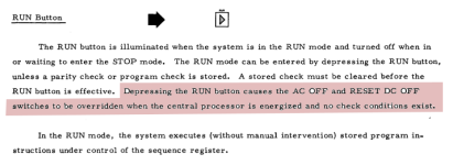
One possible clue to the extra connection form the RUN switch (an implied connection to the power supply):
1696421432449.png
I admit I'm not entirely certain what that sentence about overriding the AC and RESET DC OFF switches actually means. But having never operated one of these, I have nothing to draw from.
 
Thanks for that observation. From the wiring I suspect it means that the OFF buttons are ignored if they are pressed, so one has to stop the CPU from running before turning off the power, which makes sense. What seemed odd to me was that these buttons alone do not indicate whether the CPU is running or not as the machine may have halted itself, in which case even though the stop button was lit the power off buttons may not have worked. My field engineer friends may be able to recall exactly how these interlocks worked.

There were certainly some interesting interlocks wired into the power switching. For example, if the AC ON and AC OFF buttons were pressed simultaneously by some moron then the OFF button overrode the ON button. The same applied for the DC buttons. Pressing AC OFF or DC OFF while a program was running would have been equally moronic.

In his description of the design of the H200 its chief designer stated that, it being a cheap machine intended for the bottom end of the market, the people who used it probably wouldn't be used to working such complicated technology, so the design was aimed at being simple and foolproof (hence the clean design of the control panel without any unnecessary elements to confuse us simple folk). He wrote this in a personal document that was not intended for publication but his daughter has given me permission to quote from it in the appropriate context.

Today I was literally tidying up loose ends, in particular a loose end of wire in the harness running to the CPU connectors. It looked like it might have broken off one of the connector pins but so far as I knew all the required connections were working. The stupid part was that it was grey while almost all the other wires were orange but even so I couldn't find where it went having tested all the few grey wires visible. As a last resort I methodically pulled the wire back through the harness in loops to trace where it went. Eventually near the end of one branch of the harness I found the other end by pulling it out of the harness where it had been hiding. It had evidently been an unnecessary wire that had been cut off flush to the harness at one end but left long at the other, which was annoying but at least that was another problem solved.

Regarding the connections to the 750 ohm resistors in the previous diagram of the circuits for the CONTROL and SENSE button lights, they were all connected together but apparently not anywhere else, which implies that there was no trickle current supplied to these lights even though the circuits to supply it were provided. I can only imagine that someone realised that these lights, only being worked by the push-on-push-off switches on the buttons themselves, were not turned on and off very often in comparison to those controlled by the CPU, so supplying them with a constant trickle current could actually result in them burning out sooner than not doing so. Hence I am content to leave that mystery as it stands.

I think I have now worked out what everything within the panel is supposed to do although not always why and I am still unsure of some of the supply voltages needed to work it, but that can be determined by cautious experimentation.
 
I now have the control panel looking virtually brand new having repainted the symbols on all the buttons that needed it doing. In the coming months I will be assembling more logic boards and installing the equipment in its new home, so it will be a while before I can use the panel with what I have already built. I was taken entirely by surprise by this unexpected rapid donation of the panel so now I have my work cut out to make some real progress over the winter.

Cosmetic improvements.JPG
 
I now have the control panel looking virtually brand new having repainted the symbols on all the buttons that needed it doing. In the coming months I will be assembling more logic boards and installing the equipment in its new home, so it will be a while before I can use the panel with what I have already built. I was taken entirely by surprise by this unexpected rapid donation of the panel so now I have my work cut out to make some real progress over the winter.

View attachment 1266421
Looks great!
 
Back
Top