• Please review our updated Terms and Rules here

Horror! ABI ICT24 Chip tester Faulty - and Probable Fix

alan8086

Experienced Member
Joined
Oct 1, 2016
Messages
331
Location
Burnley, UK
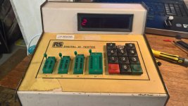
Hi - just wanted to post a process of repair for anyone faced with a similar issue - you must own an ABI ACT-24 chip tester or its rebranded RS Components brother (like mine) for tis to be relevant to you.


For the 3rd time, I found myself testing all 128 2114 RAM ICs in my IMS 8000 S100 computer


2/3rds through the first board and THIS appears!

ABI ICT24 Fault 2.jpg

First thought - this thing must be fixable - take the lid off, out with the logic board and lets Dremel/wire brush the pins on the 2 BIOS EPROMS! Put it back together and nothing! Unsurprising.

Next - calm down! Re visit the one site on the innerweb that actually has detailed info on this particular chip tester...

http://www.jammarcade.net/abi-ict-24-digital-ic-tester-tech-info/

Half way down the page, this genious has disassembled the BIOS on his unit and actually worked stuff out - as in what the fault codes mean!!! I quote:

Fault 2:
One of the IOÂ’s on PORTB is tied to VCC.
The software sets all of the IO pins on PORTB to logic LOW and reads the states back. If any pins are found to be logic HIGH on PORTB then this will result in FAULT 2.


WHATS A PORTB!!!!???

Ok, next step - further up the page he 'derives a memory map????!! Huh? As follows...

Once I had drawn it out I derived the following memory map
$0000-$3fff – ROM1
$4000-$7fff – ROM2
$8000-$87ff – RAM
8255 (IC1)
$c000 – PORTA
$c001 – PORTB
$c002 – PORTC
$c003 – Control
8255 (IC2)
$c004 – PORTA
$c005 – PORTB
$c006 – PORTC
$c007 – Control
8255 (IC3)
$c008 – PORTA
$c009 – PORTB
$c00a – PORTC
$c00b – Control
8279 (IC8)
$c00c – Data
$c00d – Control


Â….IC1...IC2...IC3 - all 8255s!! I CAN DO THIS!!

Those are the big PPI chips I can see in front of my face - lets look closer...

ABI ICT24 Logic Board.jpg

...Ok, I can see lots of bus lines going from all those PPI chips to the row of 74LS125 chips below - 'MUST' be something to do with one of those??

'If any pins are found to be logic HIGH on PORTB then this will result in FAULT 2'

My dimwit diagnosis - one of those 74LS125 chips is holding one of those PPI chip pins logic High!

Forget the Logic Probe - lets desolder all 6 of those chips and test them in my End Of The World logic chip tester - the MiniPro TL866A! and YES! It supports the 74LS125!! We can do this!

DeslderingÂ…

ABI ICT24 Removed 74LS125 ICs.jpgABI ICT24 Component Side ICs Removed.jpgABI ICT24 Solder Side Removed ICs.jpg

TESTING! TESTING! TESTING! and yessssss!! :eek:nfire::eek:nfire::eek:nfire:

ABI ICT24 Faulty 74LS125.jpg

We have a probable suspect - lets socket the thing!!

ABI ICT24 Run Out Of Sockets 02.jpg

Damnaggit - run out of 14 pin sockets!! Lets Make one!

ABI ICT24 Make Socket Dremel Before.jpgABI ICT24 Make Socket Dremel After.jpg

Now we have 6 14 pin sockets where once we had 6 74LS125's

ABI ICT24 Which is the Faulty IC.jpg

But which is the faulty chip?? THIS one...

ABI ICT24 Logic Board back in case.jpg

Do I have any spare 74LS125?? NOOOOOOOOOOOOO!!!!!!!

5 Now on Order...

https://www.ebay.co.uk/itm/112367499720

Along with 20 14 pin IC sockets:

https://www.ebay.co.uk/itm/223096101340

Stay Tuned For Next Weeks Installment! Will Bobby Die? Will Su-ellen Wake up in the shower and realise 6 weeks of filming was all a dream? WILL THE ABI ICT-24 GET FIXED!!!!!
 

Attachments

  • ABI ICT24 Fault 02.jpg
    ABI ICT24 Fault 02.jpg
    93.5 KB · Views: 1
Last edited:
I don't know why I attached a thumbnail at the end!? Don't know how that happened - Edit timed out.

Oh, I had left the chip tester in continuous test loop mode with a 2114 chip - came back a good hour and a half later and that GD74LS125A chip had died! Wont leave it that long in future!
 
Last edited:
Pleased to say my ABI ICT-24 Logic IC Tester is working again. The 5 74LS125 ICs arrived today.

I've continued to test all the ICs on my 4 16k static RAM boards and found 2 glue logic chips to be defective - more spare parts ordered!

WP_20190320_15_32_36_Pro_LI.jpgWP_20190320_15_33_45_Pro_LI.jpgWP_20190320_15_34_20_Pro_LI.jpgWP_20190320_15_34_24_Pro_LI.jpg
 
A couple of things.
I have never used a chip tester to debug equipment.
I find it unlikely that one could have that many parts failing unless there was a power supply issue or poor static handling.
Dwight
 
Same here. I've got an EPROM programmer that can identify many TTL chips, but not test them.

The LS125s are simple enough to debug in situ--they're just quad tristate buffers--no fancy memory inside of them; very straightforward.
 
And same here, I've never used an IC tester, most of the electronic boards that I repair have non-socketed logic chips, so I must identify the problem(s) and remove only the problematic chips.
However sometimes I think I'd like to have the famous HP logic comparator :)

Frank IZ8DWF
 
HP had a current probe at one time as well. Say you have a net that is stuck at 0 or +5V. The part driving the short may get hot if to +5V but otherwise which of maybe 5 or 6 loads are the problem on a soldered board. The probe had 4 close contacts. One could read out the current flowing in an IC lead. Not with any accuracy but one could still clearly see the difference between 20ma and 600ua. I evaluated one for production test years ago at Intel but even though it worked quite well, it was rare to have a new part with a shorted input. A 'scope to see voltages was usually enough to find problems and shorted nets were usually board trace or solder bridges on new units.
I'd love to have on of those probes today anyway.
Dwight
 
Yes, I know - a chip tester is a quick and dirty troubleshooting method, possibly not very quick either if you have experience and knowledge regarding the use of logic probes etc

My goal is to have a working S100 system - one that works for long enough so that I can learn the basics. Chip testers get me there quickly, but I learn little along the way.

I will check the voltages from the linear power supply with multimeter and oscilloscope, need to check the regulators too.

I also need to glue back together the head load pad that fell off the B: Drive earlier today. Maybe an excuse to buy a 3d printer? No one sells head load pads anymore!
 
I have all three HP units - logic probe, pulser and current tracer. I also have this:

http://www.jammarcade.net/abi-ict-24-digital-ic-tester-tech-info/

Plus all the chips in my IMS 8000 computer are socketed. What would be your preferred tool?

I does take about 2 hours to desocket one at a time every chip on all 4 static RAM boards, but the ABI chip tester will test every IC on there, identify unknown chips, do a continuous test loop on a device - if you look at the supported device list you will see how invaluable a tool it is. I also have an ABI DDS 40 XP - same type of tester but more advanced. You can program it in TestBASIC to test devices not currently supported.

Without these chip testers, I'd be a dead loss - this is how I worked out which two 2114 RAM chips had failed after my IMS 8000 sat on a shelf for 4 years

It now works, and my IMS8000 can now format floppy disks!

And same here, I've never used an IC tester, most of the electronic boards that I repair have non-socketed logic chips, so I must identify the problem(s) and remove only the problematic chips.
However sometimes I think I'd like to have the famous HP logic comparator :)

Frank IZ8DWF
 
HP had a current probe at one time as well. Say you have a net that is stuck at 0 or +5V. The part driving the short may get hot if to +5V but otherwise which of maybe 5 or 6 loads are the problem on a soldered board. The probe had 4 close contacts. One could read out the current flowing in an IC lead. Not with any accuracy but one could still clearly see the difference between 20ma and 600ua. I evaluated one for production test years ago at Intel but even though it worked quite well, it was rare to have a new part with a shorted input. A 'scope to see voltages was usually enough to find problems and shorted nets were usually board trace or solder bridges on new units.
I'd love to have on of those probes today anyway.
Dwight

I love HP test equipment! I have a few HP logic probes, the current tracer and the logic pulser and I've used all of them in many troubleshooting sessions. I have all original accessories and boxes as well.
Frank IZ8DWF
 
A couple of things.
I have never used a chip tester to debug equipment.
I find it unlikely that one could have that many parts failing unless there was a power supply issue or poor static handling.
Dwight

What's your opinion of the ripple on this 5V line?
WP_20190321_18_30_32_Pro_LI.jpg

Volts/Division is set to 2mv

Time base is set to 1ms/division

Probe is 10x

Its a measurement off one of the regulators on a 16k static RAM board.

I would appreciate your interpretation regarding ripple - yours will be better than mine! :D
 

Attachments

  • IMS8000 5V scope trace.jpg
    IMS8000 5V scope trace.jpg
    96.8 KB · Views: 1
Please put your horizontal on calibrated. I can't tell if it is a problem with you filter cap or the rectifier. If the rectifier is OK, you'd have peaks 8.33... milliseconds. Always keep you time base on calibrated, other wise it is just a nice picture. With a bad rectifier, it would be 16.666... milliseconds. If it is 8.333..., it is possibly a bad regulator or a bad primary filter capacitor.
Dwight

Sorry - done...

WP_20190321_21_29_22_Pro_LI.jpg

To be honest, I may be wasting your time. I just noticed the vertical position adjustment is to one extreme - cant get the trace on the centreline. If I turn the V Pos to the other extreme, the trace turns into a perfectly flat line!

Need to buy a new scope.
 
Sorry - done...

View attachment 51884

To be honest, I may be wasting your time. I just noticed the vertical position adjustment is to one extreme - cant get the trace on the centreline. If I turn the V Pos to the other extreme, the trace turns into a perfectly flat line!

Need to buy a new scope.

I see nothing wrong except you are not running in calibrated positions. I'm much more interested in the horizontal control being in the calibrated position( the one on the right with time/div ), showing two peaks. It might be interesting to know if the probe you are using is a 1x or a 10x. and we can't see the setting of the vertical input in the picture.
oops it is internal.
Dwight
 
Last edited:
Since it is not either of the values I expected to see, can you put you finger on the probe to see what 60 Hz looks like. You can change the vertical but don't change the time/div. I suspect that the scopes calibration hasn't been tended to in some time.
Dwight
 
I was on a long driving trip and while on the road it occurred to me that you are not on 60Hz but on 50Hz. Your scope is fine, it is just me that wasn't thinking. Your problem is more likely not enough capacitance for the primary filter ( the large one ). Most of these machines were designed for 60Hz. It might even be that the capacitor would work file at 60Hz. Try adding about 50% more than the size of the capacitor you have, in parallel with the current capacitor.
It might also be a weak regulator with poor isolation. Others have indicated that they have seen such pulsing leaking through with aged regulators. Don't go replacing everything.
Dwight
 
I was going to reply back and mention 50Hz. I've been unwell for a few days now. Id be surprised of my scope was anywhere near calibrated - it's old and I would think it has caps way out of spec?

So if I get another 25000uF capacitor and add it in parallel to the 50000uF cap that smooths the 8v line, that may help? Im pretty sure the main regulator is still available new for this machine too.

Thanks for getting back to me.

Alan.

I was on a long driving trip and while on the road it occurred to me that you are not on 60Hz but on 50Hz. Your scope is fine, it is just me that wasn't thinking. Your problem is more likely not enough capacitance for the primary filter ( the large one ). Most of these machines were designed for 60Hz. It might even be that the capacitor would work file at 60Hz. Try adding about 50% more than the size of the capacitor you have, in parallel with the current capacitor.
It might also be a weak regulator with poor isolation. Others have indicated that they have seen such pulsing leaking through with aged regulators. Don't go replacing everything.
Dwight
 
Back
Top