• Please review our updated Terms and Rules here

How to troubleshooting, MODEL I could not startup.

wellswang

Member
Joined
Apr 23, 2022
Messages
29
Location
Suzhou, China
Hi,

I got a MODEL I (26-1001) recently, but it could not startup.
When I push the power button, there is only a scanline on the monitor, just like lost h-sync.
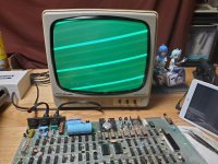
微信图片_20230820223113.jpg

First I checked the power output, +5v, +12v and -5v are all normal.
I tried to replace Z80 chip and all RAM chips, but it still display the scanlines.
I use oscilloscope to check the CLK (Z80 Pin6) signal, it's normal and at 1.77Mhz. But PIN 16,17,18, 23, 24, 25, 26 are all in HIGH state, the Z80 is not working, it's so strange.
I replaced 3 Z80 chips, still same.

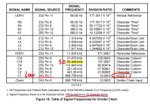
I checked following signal frequency. All signals are normal except Z50 Pin9 is about 50Khz,and Z43 Pin7 in LOW state (I think this is normal, system is not startup still in 32 Char mode.)
屏幕截图 2023-08-20 224345.png

In normal MODEL I, if pull out Z80, no CPU on the board, the system still can show some characters on the screen (in 32 col mode). But this board couldn't, it just display scanlines.
I don't know how to troubleshooting now. Please help me.

Thanks!

BR,
Wells.
 
You should check Z5/Z6/Z57 when you have bad scan, those 74Cxx chips can be trouble. I think you can replace them with 74HCxx but not 74HCTxx.
 
The address lines are outputs from the Z-80 used to specify memory locations. If any address line is not active
(stuck on one state), there will be 'garbage' (random characters) on the screen at boot. To check the address
lines, remove the DIP Shunt at position Z3 and power-up the system. If the screen fills with a pattern of
“@9@9@9@9...”, then all the address lines A0 – A9 are good. The remaining address lines A10 – A15 can
be checked for activity with a scope.

Here's why you get @9s. With the ROMs removed, the CPU reads all 1's (that is, hex FFH) whenever it
reads from the area the ROMs are supposed to be in, because an open connection tends to float to a 1
with this type of logic. Hex FFH is the RST 38H instruction. So when the processor is turned on and
fetches an instruction from 0000, it gets a RST 38H (FFH). This makes it push 0001 on the stack and
jump to address 0038. At that address it reads another FFH, so it pushes 0039 on the stack and jumps
o 0038 again. Now it's in an infinite loop. As the loop continues, the stack grows and grows, going
backward through memory. When it reaches the frame buffer between 3C00 and 3FFF, you can see
it on the screen. It looks like a string of @9's because the TRS-80 displays a 00 byte as an @
character, and 39 is an ASCII 9.

OK. So the fact that you get @9's means that the CPU is working. The data bus appears to be
working correctly too, as if a data line were stuck at 0 the CPU wouldn't be reading FF's, and if
it were stuck at 1 the CPU couldn't be writing both @'s and 9's.

There could still be a problem with the address bus or the ROMs. Note that a problem with the
ROMs might not be in the ROM chips themselves but in the sockets or circuits on the motherboard
that connect them to the rest of the system. But trying a different set of ROMs does seem like
a good idea.

pc 0000 gets FF pushes 0001 to stack jumps to 0038
pc 0038 gets FF pushes 0039 to stack jumps to 0038


Also Check the RAM IC's to see if any of them are RED Hot. The -5 VDC Supply gets shorted Internally
on those RAM IC's making them HOT.


Larry
 
OK. So the fact that you get @9's means that the CPU is working. The data bus appears to be working correctly too, as if a data line were stuck at 0 the CPU wouldn't be reading FF's, and if it were stuck at 1 the CPU couldn't be writing both @'s and 9's.

Uhm… where is the OP getting @9’s? The photos clearly show a rolling out of sync picture.

Anyway, OP, you can stop swapping out Z80s for now. The video hardware in the model I is “hardwired”, and does not rely on the CPU to initialize anything. Out of sync means something completely unrelated to the “computer part” of the machine is broken. A stable screen full of well formed garbage letters is where you need to be before you swap CPUs or memory.

First I checked the power output, +5v, +12v and -5v are all normal.

Did you check that with a VMM? If you have oscilloscope here’s a thing you should check just for laughs before proceeding: put the ’scope on the power lines and make sure +5 especially is *stable* at 5v DC, not rapidly oscillating and just *averaging* to around the target voltage. I fixed a Model I recently with that problem, it will play hell with some analog component of the sync circuits.

Not saying this is your main problem, but the regulator circuits in the Model I have more moving parts than most computers using single element linear regulators so it would be good to rule it out.
 
Guess you missed this in the comment: "To check the address lines, remove the DIP Shunt at position Z3 and power-up the system. If the screen fills with a pattern of
“@9@9@9@9...”, then all the address lines A0 – A9 are good." This is where the "@9"'s come from.
 
Guess you missed this in the comment: "To check the address lines, remove the DIP Shunt at position Z3 and power-up the system. If the screen fills with a pattern of
“@9@9@9@9...”, then all the address lines A0 – A9 are good." This is where the "@9"'s come from.

OK… but my point is that the symptoms the OP is getting make it premature to go down that troubleshooting route. The “scanlines” that are being displayed here look out of sync/rolling, and there is nothing the CPU working or not that could cause this. (The Model I does not rely on a CRTC or whatever to be initialized for it to display video; rip out *all* the memory and the CPU and it should still display garbage characters on the screen.) There’s a lower level failure here.

I checked following signal frequency. All signals are normal except Z50 Pin9 is about 50Khz

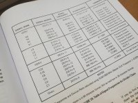
Where did you get this table? Because parts of it seem wrong. I’m looking at a copy of the original 1978 service manual, and the *important* signal on Z50 is on pin 11, IE, the horizontal drive frequency, and that should be 15.840khz, not 11.835khz. If that is actually what you’re reading that’s way off.
 
That I don't know. But it seemed to be real information. If this can't work as he says then I apologize. I am not a Model 1 expert. But it seemed like a fairly easy thing to try if it would do as he says. Yes, I see your point now that this display problem has to be fixed first.
 
You should check Z5/Z6/Z57 when you have bad scan, those 74Cxx chips can be trouble. I think you can replace them with 74HCxx but not 74HCTxx.
Anyway, OP, you can stop swapping out Z80s for now. The video hardware in the model I is “hardwired”, and does not rely on the CPU to initialize anything. Out of sync means something completely unrelated to the “computer part” of the machine is broken. A stable screen full of well formed garbage letters is where you need to be before you swap CPUs or memory.
Thanks!
I replaced Z57 with a 74HC04,the sync problem solved. The original 74C04 is failed on Pin8.
74c04_test.png

微信图片_20230821182212.jpg

After test, I found the Z80 CPU is also failed. I replaced it.
Now the TRS-80 Model I works fine.
Thanks for your kindly help!

微信图片_20230821182236.jpg
 
Where did you get this table? Because parts of it seem wrong. I’m looking at a copy of the original 1978 service manual, and the *important* signal on Z50 is on pin 11, IE, the horizontal drive frequency, and that should be 15.840khz, not 11.835khz. If that is actually what you’re reading that’s way off.

Ah... I didn't notice this...
I checked the board with a paper manual, it shows the signal Z50 pin 11 is 15.835Khz, as you mentioned. When I wrote this post, I open a pdf file to take a screenshot. In this pdf file, it says 11.835khz...
Actually is should be 15.835Khz...
I checked these two manuals version, in 1978 version 1, it says 11.835Khz but 15.835khz in version 2 (1982). Maybe it's a typo mistake.

微信图片_20230821183952.jpg

Thanks.
 
I checked these two manuals version, in 1978 version 1, it says 11.835Khz but 15.835khz in version 2 (1982). Maybe it's a typo mistake.

Huh. I guess that's a different version of the manual than I have printed out. (I have the "original* 1978 "technical manual"; the PDF of it floating around the web has "Proof Copy" stamped on the cover.) It doesn't have this info in tabular form like this. (There's a divider chain diagram that has the "important" steps on it.)

But yeah, that 11khz definitely must be a typo. Funny it happened on the value that's actually critical. ;)

I replaced Z57 with a 74HC04,the sync problem solved. The original 74C04 is failed on Pin8.

Congratulations for getting it working!

I've seen some sources gripe that a 74C04 is the only "correct" replacement, because these CMOS parts are used to drive R/C networks (including trimmer pots) that set the exact length/offset of the sync signals; the original "C" parts had very slow signal propagation so switching to HC changes the time constant of the circuit a little, but when you do the math that complaint doesn't really add up to much. (IE, it'll be maybe a couple hundred NS at most on a circuit that's adjustable across tens of microseconds.) Good to know that HC really is fine.

(That thing I said about checking for ripple on the +5v circuit relates to the R/C networks in this same area; if you have high-frequency oscillation in the power supply it can badly affect the timing of the sync signals because the capacitors in those circuits will charge at different rates between scanlines, resulting in wobble/rolling/complete loss of hsync.)
 
Hi Wellswang - Please to see your M1 working OK. Please may I use a couple of your photos for a short article in the Sept edition of TRS8BIT. (see trs-80.org.uk) Full accreditation will be given. I wonder if any others have had problems with the typo over the years?
 
Hi Wellswang - Please to see your M1 working OK. Please may I use a couple of your photos for a short article in the Sept edition of TRS8BIT. (see trs-80.org.uk) Full accreditation will be given. I wonder if any others have had problems with the typo over the years?
That's OK. Thanks!
 
Back
Top