• Please review our updated Terms and Rules here

HxC and Model II/16

dittman

Veteran Member
Joined
Jul 31, 2017
Messages
685
Location
Plano, TX
I have a Model II and am trying to use an HxC SD floppy emulator with it using one of Mark's fd50to34 adapter cards.

I was able to boot from the TRSDOS 2.0 and all the CP/M images (except for CP/M Plus) from the Model II archive. I couldn't use the HxC as both drives 0 and 1 since the Model II controller only supports one internal drive (thanks to that reminder from Mark). I swapped in the floppy controller from my deal Model 16 and was then able to use the HxC as drives 0 and 1. I tried to install from the P&T CP/M image which wants to format and install a working copy on the disk in drive B. I copied the boot image and tried to use the copy for the disk in drive B but it formats up to track 43 and then fails on track 44. I'm guessing this is related to the TG43 signal but I've not used many systems with 8" floppy drives in the past.

Is anyone using an HxC with Mark's adapter on a Model II/12/16? If so, is there any trick to the jumper settings on Mark's adapter or the setting for the HxC?
 
I have a Model II that behaves the same way. It won't write past track 43 with HxC or real floppy. I have not yet looked into it further as I have another Model II without the issue. Both have the later M16 FDC card. Have you tried with a real floppy?
 
I haven't tried formatting a real floppy. I need to make a new cable so I can have the HxC and floppy drive connected at the same time.
 
I couldn't use the HxC as both drives 0 and 1 since the Model II controller only supports one internal drive (thanks to that reminder from Mark).

I was testing some newly acquired Model II cards today and one of them happened to be the early floppy controller or FDC board. Remembering this thread, I decided to test it with my HxC and it actually does work very well using both drives on the HxC. I suspect your floppy controller needs some adjusting or repair.

BTW, I have never had much luck formatting Model II disks with the HxC. I have to look into this further.
 
I can read and write okay with both floppy controllers. It was formatting that was failing, so if that's not working for you as well then maybe I'm okay.

I tried connecting up my external drive bay and it's not working. The power LED doesn't come on and the Model II won't boot with it connected so I'll need to open it up and look after I get over this cold.

I do have an issue where I can't boot the CP/M Plus, TRSDOS-II 4.2, or Model 16 Systems disk (if I install my 68000 CPU and memory) images. That may be something else.
 
BTW, I have never had much luck formatting Model II disks with the HxC. I have to look into this further.

CPM "seems" to format OK on the Model II with the HxC but I could not get LSDOS or TRSDOS to format.
Same goes when formatting the HxC on the System80. TRSDOS aborts with a motor fast error and NEWDOS aborts with a motor slow error.
I patched TRSDOS to format OK and EVAD did some excellent detective work via the CRO and got NEWDOS to format OK.

Off the top if my head I can't remember the exact details but I think the HxC is a bit slack on the timing of it's index pulse.
Formats a complete track and then decides it might be a good idea to send an index pulse.
 
When I try under CP/M format seems to work until it hits track 44, then fails.

Which version of the HxC do you have?
 
I doubt the HxC does anything useful with the track 43 signal. You might try just disconnecting it
from the cable. Activity on that line might be causing issue in the emulator. Since it is not a real disk,
it should ignore the signal from the controller. It may be that it is just doing something wrong. Since it
is working on the lower tracks, disconnecting the signal might be a good idea.
On a real disk it would change the write current. I can't imagine what a emulator would do with it.
For double density, some controllers also change precomp. That may cause issues for the HxC.
I'd not considered that as a possible issue.
Dwight
 
Last edited:
There's a jumper on the fd50to34 board. I've tried changing it without luck.

There are two or three different versions of the HxC as well as Gotek emulators with HxC firmware. It would be interesting to see which version people have and whether or not they can format.
 
@Alphasite

I think you are using a 'Late Design' Floppydisk Controller, item number: 8709198 in your Model II
In that case you have to rewire the flat cables.
At first you have to open the holes on the PCB for the 50 pin header, just below the 50 finger edge connector.
You have to solder a 50 pin header in these 50 pin holes.
Then you must connect the internal disk drive and the external floppy connector to this header.
In this situation you can use 2 drives on this connection.
If you want to connect more drives you have to connect them to the 50 finger edge connector on the FDC adapter
You have to set the jumpers on this adapter according this jumper table.
I hope this solve your connection problem.

FDC-Late.jpg
 
@Alphasite

I think you are using a 'Late Design' Floppydisk Controller, item number: 8709198 in your Model II
In that case you have to rewire the flat cables.
At first you have to open the holes on the PCB for the 50 pin header, just below the 50 finger edge connector.
You have to solder a 50 pin header in these 50 pin holes.
Then you must connect the internal disk drive and the external floppy connector to this header.
In this situation you can use 2 drives on this connection.
If you want to connect more drives you have to connect them to the 50 finger edge connector on the FDC adapter
You have to set the jumpers on this adapter according this jumper table.
I hope this solve your connection problem.

View attachment 42031

My Model II and 16 controller boards were the same except for jumper T-U and an extra wire soldered on the Model 16 board. When I changed the jumper on the Model II board I was able to access two internal drives.
 
My Model II and 16 controller boards were the same except for jumper T-U and an extra wire soldered on the Model 16 board. When I changed the jumper on the Model II board I was able to access two internal drives.

Ok makes sense, looks like your hardware is working as expected. Now we need to look into the HxC formatting flaw.
 
I replaced the Rifa caps on my Model 16 power supply and tested it in the Model II. The LED didn't light and the screen was dark. Are the power supplies compatible? I thought they were. If they are then there's more at fault than the blown caps.

I got another Model II power supply a couple of days ago. It's a different design than the one that came in my Model II. It's got a different set of Rifa caps so I need to order more before I try to power it up.
 
One other question is whether the order of the boards makes a difference. The Service Manual says CPU, disk, memory, and video/keyboard, but mine came with them as CPU, video/keyboard, memory, and disk. I read that you don't want to leave any empty slots between boards but nothing about the order other than what's in the SM.
 
I replaced the Rifa caps on my Model 16 power supply and tested it in the Model II. The LED didn't light and the screen was dark. Are the power supplies compatible? I thought they were. If they are then there's more at fault than the blown caps.

I got another Model II power supply a couple of days ago. It's a different design than the one that came in my Model II. It's got a different set of Rifa caps so I need to order more before I try to power it up.

The power supplies are compatible but the older ones will not have enough output to supply the fuller cages of the M16. What are the Model #s? You should see one of A11080, A11081 or A11082.
 
One other question is whether the order of the boards makes a difference. The Service Manual says CPU, disk, memory, and video/keyboard, but mine came with them as CPU, video/keyboard, memory, and disk. I read that you don't want to leave any empty slots between boards but nothing about the order other than what's in the SM.

There are some special rules on the card arrangement, but primarily that the CPU card must be first and that there should be no gaps between the Z80 cards that require to be on the interrupt chain. Page II.2 of the Tandy Notes And Jumpers document has a detailed explanation on all of this. There are also several PSU related tech bulletins in the Model II Technical Bulletins you may want to check out. It's probably a good idea to perform the PS bench tests as documented in the Service Manual so that you have a baseline on how the PS is performing.

The docs are at https://github.com/pski/model2archive/tree/master/Hardware
 
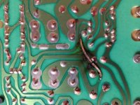
The one that came in my Model II is an A11081. Two of the caps blew and I replaced them. While I had the PS out to replace them I found the following on the back (and it was working like this) and repaired the burned out trace with a wire:

ModelIIPSBurn.jpg

However, the PS wouldn't work. I removed the wire and it worked again. There's a random shake to the display so that needs checked.

The PS I got from a seller on eBay is an A11080. I haven't tested it yet as I need to replace the caps first and I need to order more.

I tested the Model 16 boards in the Model II. Because the Model II power supply doesn't have enough power to run all the boards I disconnected the power to the floppy drive to reduce the load and loaded the diags off the HxC. All the boards from the Model 16 worked except for the Z80 CPU (a Rev. D). I need to figure out why that one doesn't work.

I just installed the Model 16 power supply in the Model II after replacing the caps to test it. It will go back in the Model 16 after I repair it and clean up the Model 16.
 
There are some special rules on the card arrangement, but primarily that the CPU card must be first and that there should be no gaps between the Z80 cards that require to be on the interrupt chain. Page II.2 of the Tandy Notes And Jumpers document has a detailed explanation on all of this. There are also several PSU related tech bulletins in the Model II Technical Bulletins you may want to check out. It's probably a good idea to perform the PS bench tests as documented in the Service Manual so that you have a baseline on how the PS is performing.

The docs are at https://github.com/pski/model2archive/tree/master/Hardware

Thanks. It would be easier to test all this if it wasn't such a pain to swap the power supplies. To be safe the CRT needs to be discharged to be safe and getting the assembly in and out is time-consuming.
 
The one that came in my Model II is an A11081. Two of the caps blew and I replaced them. While I had the PS out to replace them I found the following on the back (and it was working like this) and repaired the burned out trace with a wire:

View attachment 42070

However, the PS wouldn't work. I removed the wire and it worked again. There's a random shake to the display so that needs checked.

The PS I got from a seller on eBay is an A11080. I haven't tested it yet as I need to replace the caps first and I need to order more.

I tested the Model 16 boards in the Model II. Because the Model II power supply doesn't have enough power to run all the boards I disconnected the power to the floppy drive to reduce the load and loaded the diags off the HxC. All the boards from the Model 16 worked except for the Z80 CPU (a Rev. D). I need to figure out why that one doesn't work.

I just installed the Model 16 power supply in the Model II after replacing the caps to test it. It will go back in the Model 16 after I repair it and clean up the Model 16.

I suspect the burned trace went to something that was shorted. It is likely a bad capacitor.
Removing traces is an interesting way of fixing things. One would wonder why they put that trace there ( maybe as a board heater ;)
Dwight
 
I suspect the burned trace went to something that was shorted. It is likely a bad capacitor.
Removing traces is an interesting way of fixing things. One would wonder why they put that trace there ( maybe as a board heater ;)
Dwight

It seems to have burned long before I got the system and was working.

I was really surprised that fixing the trace resulted in the power supply not working. A quick glance looks like it's between an inductor and resistor. I need to trace it out and compare to the schematics.
 
Back
Top