• Please review our updated Terms and Rules here

I need help to configure a DEC MRV11-C board for the usage with MXV11-A boot roms.

klapperp

Experienced Member
Joined
Dec 14, 2021
Messages
84
Location
Austria
Dear Comunity!

Is there anybody who can help me to configure a DEC MRV11-C board in a way to use it with PDP11 boot roms.
I read that at least the MXV11-A boot roms are supposed to work together with this board.

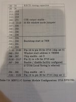
I configured my MXV11-C board for Intel 2716 chips as documented in the "Digital_Microcomputer_Processor_Handbook_1979_80" and jumpered it to work in memory mapped mode. Then I programed two Intel 2716 Eproms with the dumps of the MXV11-A ROMs 23-039D1 and 23-040D1.

As bootstrap starting address I tried: 003000 and 007000 with the chips, installed in XE43 and XE44 as well as 013000 and 017000 with the chips, installed in XE37 and XE38, without any success :-(
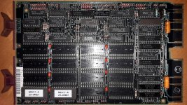
I attached a picture of the MXV11-C where you can see the jumpers as well as two pages from the "Digital_Microcomputer_Processor_Handbook_1979_80" where I documented my configuration attempt.

What am I doing wrong? Is there a wizard who can help?

Many thanks in advance and kind regards

// Peter
 

Attachments

  • 20240218_185520.jpg
    20240218_185520.jpg
    5.9 MB · Views: 8
  • SCAN_20240218_193233_000033.jpg
    1.1 MB · Views: 7
  • SCAN_20240218_193233_000034.jpg
    1.3 MB · Views: 3
In ODT can you read the contents of the PROM's? Do they appear at the correct address? Does the MXV11-A bootstrap interfere with the window-mapping?
 
The manual says:

To configure this module, see the flowchart shown in the figure below.
To avoid overlooking any jumpers, please conform to this flowchart.

Flowchart.jpg

The MRV11-C ROM module operates in either the direct addressing
mode or the window mapping mode. The user determines the desired
operating mode and must configure the module as detailed. The con-
figuration of these two modes and the optimal bootstrap area is con-
trolled in the module by three multiplexers, as shown in this figure: the
(CSR) low byte and direct address MUX, the (CSR) high byte MUX and
the boot MUX. The outputs of these multiplexers are used by the
decoder to determine the proper high-order address to the read-only
memory array via a set of configuration jumpers.
In the direct address mode, the high-bit address information to the
decoder comes from the low byte and direct address multiplexer. A
set of configuration jumpers are used to connect this MUX to the bus
address lines of the Direct Address Latch.
In the window-mapped mode, the address information to the decoder
comes from both the low byte and direct address multiplexer and from
the high byte multiplexer. The configuration jumpers are used here to
connect the multiplexers to the low byte and high byte, respectively, of
the Control and Status Register (CSR). Each byte of the CSR is then
used by the program to define that portion of the ROM that is ac-
cessed by the two mapping windows.
When the bootstrap is used, the address information in the decoder is
provided by the boot multiplexer. The configuration jumpers here are
used to define where the starting address is for the boot and to route
this address information to the memory array.
Additional jumpers are provided to allow the user to tailor the MRV11-
C to specific system needs, in addition to mode and memory array
size. The bootstrap option can be used by either mode or can be
disabled. Once the size and number of chips is determined, the chip
enable jumpers can be selected. The chip access time must be
selected to accommodate the chips with the slowest access time. The
user can also inhibit the DATIO bus cycles, which are attempts to write
into the read-only memory.

Further in the manual I found the following:

Status Register description when using more than one MRV11-C. The
recommended value of the window starting address is 760000. This
places the windows at the bottom of the I/O page and is thus compati-
ble with both 16-bit and 18-bit addressing. It is this recommended
value that is used by the MXV11-A2 bootstrap.

window_starting_address.jpg

Unfortunately I did not find anything about the MXV11-A2 bootroms themselves.

I will now try to read the contents of the boot roms with ODT.

Any other suggestions what else I can do?

Thanks in advance,
// Peter
 
This caught my attention because I have an MRV11-C board also. I've been working on understanding the BDV11 bootstrap board for a while. The goal is to be able to boot MSCP devices using an 11/03 processor. My understanding is that the MXV11-A2 rom will boot a TU58 and nothing else, is that want you need? The ROM on the BDV11 will boot; RK05, RL01/2, RX01 and RX02 along with some DecNet bootstraps.
I read the contents of the BDV11 ROM using PDP11GUI and having it disassemble the dump. It is difficult because of the paging. I'm obsessed with this because the documentation for the BDV11 alludes to the use of User ROM's and code.
 
@dith: I am happy that with you there is a 2nd one who is working on this issue.

As far as I understood, the BDV11 ROMs are not compartible with MRV11-C but the the MXV11-A2 ROMs are supposed to be. You are right, a TU58 bootstrap is not my final interest but a first step to understand the way how MRV11-C needs to be configured. Once the MXV11-A2 ROMs work correctly I will try to split the MXV11-B2 ROMs into chunks. Then I will try to make them work, because they are, as fas as I understand, compatible with MRV11-C, but just too big. But as long as the MXV-A2 ROMs do not work in the way as they are supposed to, it makes no sense for me to play with other stuff.

Maybe we can both first make the MXV11-A2 roms work on our MRV11-C boards and later try to split the MXV11-B2 roms and make them work.

I will be happy hearing from you when you have success and also what you did to make it happen.

// Peter
 
Last edited:
I've also gone down the Bootstrap rabbit hole. The BDV11 manual implies that if you enter an unrecognized device, it only accepts RK,DL,DX, DY and I think H, it will jump to execute code in the user ROM. Not much more detail than that. Of course to produce your own bootstrap ROM you need the PROM (2708/16), a PROM programmer and compiled and split into high byte/low byte code. I've collected a series of bootstrap macro code to help get me going. The incompatibility of the MXV11-B2 bootstrap seems to be the address of the paging register. I don't know if the MRV11-C paging register uses a standard or not address.
 
If memory serves me correctly, the MXV11-A bootstrap ROMs were generally 256 WORD bootstraps for either the TU58 or a disk.

The selection between the two bootstraps was undertaken by a wire link for address line A9 - to select one of the 256 WORD sections of the bootstrap ROMs.

The normal bootstrap address will be a window of 256 WORDS within the I/O space (173000 for 16-bit machines and 773000 for 18-bit machines).

You will need to set the MRV11-C to window mode and a start address of 173000/773000.

You can then set-up the CPU to bootstrap from 173000/773000.

I would suggest powering up to enter ODT first and then use ODT to make sure the TU58 bootstrap appears in the window starting at 173000/773000.

Also, make sure to get the high and low byte ROMs installed the correct way around...

Dave
 
Last edited:
@Dave: Thank you for your reply.

What is confusing me is the fact that the MXV11-A ROMs fit on two 2k*8 typ 2716 EPROMS and therefor the MRV11-C board needs to be configured for 32K Bytes of memory.
The MRV11-C board has 16 sockets (8 pairs for low and high) for EPROMs and the manual says that one can configure the following start addresses for the boot multiplexer in this mode:
bootstrap_addresses.jpg
Also I think that the configurable addresses are related to the sockets where the chips are actually installed.

My questions are now:
1.) On which sockets should the the chips be installed?
2.) Which of these possible addresses should be configured?

Further help is very appreciated!

Many thanks in advance
// Peter
 
But is all of the MXV11-A boot EPROM space actually used or is only the first 2*256 WORDS used with the remainder being unused?

I have shutdown my laptop and will be going out tonight. I will catch up with you again tomorrow. You might have solved your problems by then?

We use the MRV11-C board for our own (non-DEC) bootstraps. We have a good set-up manual, but I will have to go and pull it out.

Dave
 
I pulled my manual out.

There is a very nice description of how to configure an MRV11-D board and a pretty picture of where to install the high and low boot EPROMS.

Unfortunately, I only have the description for the MRV11-C board, but no picture. I will have to read the words... That is definitely going to be tomorrow.

The MXV11-A ROMs appear to be 1KBytes each, so the full complement is 1 KWORDS.

Dave
 
@Dave: Yes I can confirm that the 2716 PROM dumps are only half full, so each ROM holds 1KByte of data, which gives together 1 KWord.

When I take a look at the DEC manual at the section where the "Bootstrap Startin Addresses" are explained, I read it as following:

When I have chips which give me, when fully populated, together 16KBytes of memory, I have 8 possible starting addresses.
For a maximum 32KBytes of total memory (which is my case with type 2716 chips) I have 16 possible starting addresses.
For 64 KBytes of total memory with e.g. type 2732 chips I have 32 possible starting addresses.

When I understand the board correctly this means, each CHIP SET location (a pair of two sockets) has it's possible starting addresses.
For a 16KBytes configuration each CHIP SET is related to one possible starting address, for a 32KBytes configuration there are two possible starting addresses for each CHIP SET and for a 64KBytes configuration there are four possible starting addresses.

When I want now, that something is located at 773000 (173000), I think that I have to the select starting address 013000, relative to 760000 and place the chips at the location for CHIP SET 1 XE37 and XE38.
I tried this but without success - maybe I don't understand the manual an I am doing something completely wrong, therefor please help me to understand ;-)

Many thanks again in advance
// Peter
 
I will have a read of the MRV11-C manual when I get a bit of time. I can compare that with my manual.

Dave
 
The MRV11-C manual is not exactly 'user friendly' is it!

I will go back to our own manual and read the words to see how we configure a bootstrap board. If I can't work it out, I know a man who can...

 Dave
 
This is the configuration I have for an MRV11-C board using 2716 bootstrap EPROMS. I believe the boot chips go into set 0. XE43 (low byte) and XE44 (high byte).

The last set of links (TU58 Local Saving) I don't belive are required for boot only.

How does this differ from what you have tried?

Dave
 

Attachments

  • 20240222_205049.jpg
    20240222_205049.jpg
    1.3 MB · Views: 9
Last edited:
I am browsing the Microcomputer Products Handbook for the MRV11-C, there are 129 wire wrap pins! Yikes! This must be the gold standard for "Some Assembly Required".
 
@Dave: Thank you very much! My configuration is mostly the same, except J67 - J68 is off in my configuration. I will connect these two and retry.
If this does not lead to success, I will continue try to play with chip set locations and bootstrap start addresses.
The good thing is, that I understood the manual correctly when I compare my config with your doc ;-)

@dtih: In deed, that's the cellange - but it is an interesting activity for rainy days.

If one of you guys has time to try it out as well, to boot a PDP11 with the help of an MRV11-C, I am very interested in the solution.

I will of course let you know the outcome of my experiments

// Peter
 
Last edited:
I think 67-68 is a fundamental pin configuration.

It seems like a simple configuration change to make and test.

Good luck...

Dave
 
@daver2, @dtih there are some results but unfortunately without success of booting my PDP11.

I have a board from Universal Instruments with boot ROMs, with which I can boot at least from an RX02. I can read the content of these ROMs with ODT.

20240202_085005.jpg
See: 240224_odt_read_universal_orig_at_773000.txt

When I jumper the MRV11-C to the boot window address 013000 and plug these Universal Instruments ROMs at the chipset position 1, I can read the content of these ROMs as well with ODT and get the same result.

See: 240224_odt_read_universal_at_773000.txt

Unfortunately the Universal Instruments boot ROMs do not work on the MRV11-C.

When I plug the MXV11-A boot ROMs to my MRV11-C at the chipset position 1, I can also read the content of the ROMs with ODT.

20240224_172713.jpg
See: 240224_odt_read_mxv11a_pdp11gui_at_773000.txt

But wehn I enter 773000G at the ODT, nothing happens (it seems to load something because I get no feedback in ODT but nothing happens)

When I jumper my MXV11-C board to the first boot window address 003000 and plug the MXV11-A boot roms to the chipset position 0, I can also read something at 773000 with ODT, but it is different and also nothing boots.

20240224_220122.jpg
See: 240224_odt_read_mxv11a_pdp11gui_at_003000.txt

Maybe one of you guys has an idea what else I can try?

Again many thanks in advance for your help,

// Peter
 

Attachments

  • 240224_odt_read_mxv11a_at_003000.txt
    3.8 KB · Views: 3
  • 240224_odt_read_mxv11a_at_773000.txt
    3.8 KB · Views: 4
  • 240224_odt_read_universal_at_773000.txt
    3.8 KB · Views: 2
  • 240224_odt_read_universal_orig_at_773000.txt
    3.8 KB · Views: 2
The first thing I note in the file 240224_odt_read_mxv11a_at_003000.txt is that the low byte ROM bits all read logical '1' (i.e. the word value ends in 377 or 777) indicating that either:

1. The low byte EPROM was inserted into the wrong socket.

2. The low byte EPROM was inserted into the correct socket, but inserted incorrectly.

3. Something else is causing the low byte to not read correctly (configuration, fault etc.).

I will now check the bootstrap itself (in the file I can read).

EDIT: The high byte ROM (of the first few words at least) match - so the problem is definitely related to the low byte ROM.

Dave
 
Last edited:
Back
Top