• Please review our updated Terms and Rules here

I overclocked my IBM 5150...

Can you successfully use cassettes with the overclocked 5150? I am serious. I remember the question of CPU speed versus the cassette interface coming up a few times in the past so this might be the best chance to prove things.
Yes. I've tested this extensively recently
 
View attachment 1033961

OK, so I've been a very busy boy since I last posted in this thread.

I had some PC-SPRINT PCBs manufactured (pictured above) using Retro Canada's KiCAD / gerber files and have been using one in my 5150 for the past week. I have an NEC V20 CPU and an 8087-2 installed, as well as 150ns RAM. I built my PC-SPRINT with a 21.47727MHz crystal giving a CPU clock speed of 7.16MHz. This is the same as the Tandy 1000 EX and HX, for what it's worth.

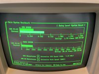
I've had zero problems so far and have tested with various games with a CGA and an EGA card. The performance difference is pretty staggering, actually. I've run a whole load of benchmarks and the improvements are in the 50-55% range across the board. I just leave the turbo mode enabled at all times, even when booting - incidentally, cold boot time has been reduced from 1:02 to 43 seconds. The new reset button is handy too.

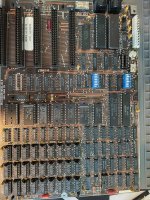
But it doesn't end there. As others raised some concerns about DMA I also decided to learn some KiCAD and circuit design and work on my own "PC-SPRINT v2". These arrived from PCBWay today and I have assembled one:

View attachment 1033960
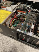
..and installed it:

View attachment 1033962

The new version adds some additional logic to incorporate the DMA signals previously identified by Sergey Kiselev:

View attachment 1033963

I initially built this with a rather ambitious 24MHz crystal but the PC would freeze instantly with it enabled (even at the DOS prompt) so I have downgraded to a 22.1184MHz crystal (7.37MHz CPU clock) and that has worked perfectly fine in my limited testing so far.

Note that I haven't hooked up the DMA side of things yet but that's next on the todo list. I think I found the right places on the motherboard based on the Technical Reference but I want to confirm with an oscilloscope before I do anything too hasty, especially as it's all working fine so far anyway.

I documented the whole project over on GitHub for future generations who may stumble across this and get intrigued like I (and others) did: https://github.com/reesclissold/pc-sprint

It's very much a work in progress but I've added all the details on the benchmarks I've run so far as well as all of the files for the v2. There are probably a few errors in there as I'm still learning but I felt it made sense to put all my findings in one place.
I've recently become rather interested in overclocking the 5150 myself. Looks like I'm late to this discussion, but would like to know if any further progress has been made on this rev2 pc-sprint board you made... Seems like 21.4mhz is as best I can get with the original sprint design as well, and your improved version appears a bit more streamline than the Sergey Kiselev project;)
 
I’m currently running my PC-SPRINT with a 22.1184 mhz crystal with the v20-16 at 7.37 mhz. Seems stable for the most part, but need to do some more tests!
 

Attachments

  • IMG_3645.jpeg
    IMG_3645.jpeg
    2.4 MB · Views: 20
  • IMG_3639.jpeg
    IMG_3639.jpeg
    2.4 MB · Views: 20
I don't know if it's responsible to suggest doing this.......
But recently I desoldered the first row of ram on mine. Installed 100ns ram in all banks and and was able to push a 24.5mhz crystal :)1000000068.jpg1000000069.jpg
 
This is my board w/out the jumper I had to install when I replaced the clock gen driver with the 18p socket... nicked a trace :-( Don't know much about the ram, but I might be up for pushing it further!
 

Attachments

  • IMG_3614.jpeg
    IMG_3614.jpeg
    702.8 KB · Views: 20
Using some software called speed600.exe clock is at 8.16mhz but low balls actual CPU speed at 7.9ish.
Says "performs like 6mhz AT"
 
Those brown boards are indeed prone to traces lifting during desolder. I didn't take any chances and just cooked the soldered ram with heat gun till they either pulled out in one piece or in several. Looking back perhaps cutting them out and desoldering just the legs would have been smarter.
 
And for the ram, was the >100ns your bottle neck? Looks like my board has 150ns ram in there now... I need to do some more research on the ram limitations, etc.
 
I googled a ns to mhz converter and found that:
7mhz = 142.85ns
8mhz = 125ns
9mhz = 111.111ns
I figured that running my CPU above 7mhz was pushing the limits of my original 150ns ram chips. 100ns ram installed allowed for me to achieve nearly 8mhz CPU speed. However in theory, if ram was the only bottle neck then I should have been able to reach 9.5 or 10mhz.
Tapping into the DMA cycles as previously mentioned in this forum seems to be the key to pushing forward. This would automatically turn off the overclock before a crash can occur... At least that's how I understand it🤔
 
Indeed there is more to it.

Technically an XT can’t consecutively access ram every clock cycle meaning it’s not really reading ram at the full 4.77mhz either.

The memory control circuitry and other chips between also have latency.

The odd part is sometimes you could overclock a lot but your ram then had to be far faster than you would expect. Aka 50/60ns because the slow logic + ram latency was your cycle limit

Occasionally swapping out some of the logic chips on the board with faster versions would make it just fast enough to hit another speed grade.

I remember a few folks back in the day that swapped all their ram for s-ram , no idea how this was accomplished back then.
 
Last edited:
s-ram conversion 🤯This rabbit might never end lol.
As for logic chip swapping? I have began to socket and swap a few. In Sergey's xi 8088 project he recommended using SN74ACT11N chips instead of 74LS04's. So I replaced those first attached a pic of where they are below1000000074.jpg
 
I'm going to have to get a second motherboard to go after with all this... This is quickly going to be a Ship of Theseus kind of thing, huh? haha
 
So here’s where I’m heading next… First, I’m going to get some additional crystals and see how far I can take it without messing with the ram… Right now I’m using a 22.184mhz crystal and will start stepping up from there. On the board currently are soldered in D4164C-15 chips in Bank 0, which I THINK is 150ns ram although I can’t find a data sheet. The other 3 banks are fully populated with a chip that says “JAPAN 849369, NEC OV A02358, 8349 Y H 224” which I can’t seem to find any info on so far either… if anyone has info let me know! I’d be willing to solder in sockets and upgrade them all potentially… There’s pics of the board in a previous post if you want to take a look.
 
On the board currently are soldered in D4164C-15 chips in Bank 0, which I THINK is 150ns ram although I can’t find a data sheet.
NEC's µPD4164C-15. NEC typically do not print the "µP" bit on the chip. 150 ns. Data sheet at [here].

So here’s where I’m heading next… First, I’m going to get some additional crystals and see how far I can take it without messing with the ram…
And certain other chips.
 
Back
Top