• Please review our updated Terms and Rules here

I think i killer my 5170 Mainboard

Frank4545

New Member
Joined
Apr 13, 2024
Messages
6
Hey there,

this is my very first post in this Forum. I did something extremely stupid and i think that it could have fried my entire 5170 Rev 1. Mainboard. I hope that maybe someone with more understanding can tell me how bad i have failed and what can be done.

So i recently got this board and it powered up, no Problem, but only 256K of Ram was showing with both banks populated. Found a bad chip through swapping and got myself a replacement chip.

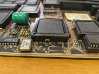
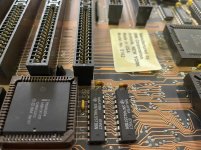
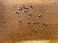
When i powered the system up it again only showed 256K. So i confirmed that the replacement chip was working and started to look for visible damage near the ram banks. Then i saw that the terminators on RN1 had what appeared to be a visible crack on it. And that was when trouble unfold. I took out a multimeter in diode mode and measured the terminators on RN1, RN2 and RN3 to see if RN1 behave different to the others, well aware that i dont really have a clou. End of the story is that the board appears to be absolutely dead now, showing no postcodes at all on a diagnostics card.

Can someone please tell me what i have damaged and if something can be done

Thanks
 
Hello @Frank4545 .

So, I don’t think that you killed your board. Early IBM motherboards, like yours, suffer from shorted tantalum capacitors on the main power (5/12vdc) circuits. When one shorts, it can pop, or it can just cause your power supply to go into shutdown, to protect itself.

Please check power, with the board on, at your P8 and P9 connectors, to verify all the voltages.

Here is an example pinout for the connectors:

There are lots of other troubleshooting steps that you can take, but this is a good first step.

Good luck!
- Alex
 
Early IBM motherboards, like yours, suffer from shorted tantalum capacitors on the main power (5/12vdc) circuits.
Yes, it is correct! The tantalum capacitors on my 5162 are shown below. I had to replace all of them.
 

Attachments

  • 微信图片_20240415140653.jpg
    微信图片_20240415140653.jpg
    254.7 KB · Views: 18
  • 微信图片_20240415140701.jpg
    微信图片_20240415140701.jpg
    292 KB · Views: 18
  • 微信图片_20240415140705.jpg
    微信图片_20240415140705.jpg
    451.7 KB · Views: 18
Can someone please tell me what i have damaged ...
Sometimes, things are co-incidental. Today, in support of another active thread, I flicked the red power switch on my IBM 5170. 'Dead as a doornail'. Not even the power supply fan was turning. The 5170 was working fine a week or so ago. Fault traced to a short-circuited capacitor on the hard/floppy controller, a well known problem on that card (but the first time that I have encountered it). I cut that capacitor off (which I will replace tomorrow). The 5170 powered on, but this time, a 201 error was displayed, pointing to address 512 KB. Traced to a faulty RAM chip on the 'IBM 128KB Memory Expansion Option' card.

And so your "absolutely dead now" may simply be coincidental with you going in with a multimeter.

'Dead motherboard' has many many possible causes.

Ajacocks post is logical. Check the voltages first, and the result steers the diagnosis direction. Do this whilst the P8 and P9 connectors are plugged into the motherboard (the power supply needs an adequate load).

Another P8+P9 diagram is at [here].
 
Thank you for your replies guys.

I will test the voltages soon and give you an update. As i mentioned the mainboard turns on but there is no sign of live whatsoever on the diagnostics card.

Is there a guide to savely measure the voltages on a at-mainboard while powered on using a multimeter? I think i can do it but i have never done it before.

Thanks.
 
... showing no postcodes at all on a diagnostics card.
As i mentioned the mainboard turns on but there is no sign of live whatsoever on the diagnostics card.
Well, no POST codes, but from my understanding, you are seeing the card's +5V LED lit. But note that seeing the +5V LED lit does not necessarily mean that +5 volts is present. Some POST cards are quite crude. For example, some may light the +5V LED even if the +5V line has, say, +4 volts on it (and +4 volts is not enough). That is why an actual measurement of the voltages is prudent.

Is there a guide to savely measure the voltages on a at-mainboard while powered on using a multimeter? I think i can do it but i have never done it before.
1. Refer to the diagram on the web page at [here]. Ignore everything else, because that page is for a different computer.
2. Put your multimeter into DC voltage mode.
3. Negative (black) meter lead to any of the black pins. Example photo at [here].
4. Positive (red) meter lead to the pin of the voltage to be measured.

Note that POWER GOOD (the orange wire) is not a voltage supply. It is a signal that the power supply sends to the motherboard. The signal voltage expected is + 2.4 volts or greater.
 
Hi Frank4545,

Besides checking what was already said in this thread, I would like to add that you need to check RN1 since you mentioned a crack.
You can measure the opposing pins with eachother with your meter in ohms mode which should show around 30 ohms for each of the 8 resistors inside RN1.
So measure pin 1 with pin 16, pin 2 with pin 15, and so on. Just clearly confirm for yourself that RN1 is not faulty or contains a loose/intermittent contact due to the crack you saw.

Kind regards,

Rodney
 
Thank you all for your help.

Ok, i checked the voltages while the board was running. It seems that the values i got seem to be fine. All rails were there with deviations between +0,1-0,2V. Power Good Signal was at 5,34V is that ok? I used a random AT-PSU for the test.

I also put the probes of my multimeter on the terminators at RN1, RN2 and RN3 again and measured the opposing pins. By the way. This was exaclty what i did before the board refused to start. They were all at 30 - 31 Ohm readings.
Meanwhile i also checked the 80286 cpu in a another 5170 Rev 3. board and the processor is definetly working.

Is there anything particular i would have to check next?
 
I checked the voltages on the data-in pins of the ramchips too. The row next to the terminators is showing 4.7V and all the other chips are showing 1.78 - 1.8V.
 
... and measured the terminators on RN1, RN2 and RN3 ...
... on the terminators at RN1, RN2 and RN3 again ..
These are resistor networks ('RN'). Only sometimes are resistor networks used in a termination role. Looking at the circuit diagram of the type 1 motherboard, RN1 through RN3 are not used as terminators.

Ok, i checked the voltages while the board was running. It seems that the values i got seem to be fine. All rails were there with deviations between +0,1-0,2V.
Good.

Power Good Signal was at 5,34V is that ok?
Yes.
+5.34V will be interpreted as a TTL high level.

I checked the voltages on the data-in pins of the ramchips too. The row next to the terminators is showing 4.7V and all the other chips are showing 1.78 - 1.8V.
A multimeter is unsuitable for data pins. And measuring data pins is too early at this point in diagnosis (and may end up have being a waste of time).

I also put the probes of my multimeter on the terminators at RN1, RN2 and RN3 again and measured the opposing pins. By the way. This was exaclty what i did before the board refused to start. They were all at 30 - 31 Ohm readings.
So, a faulty RN1 ruled out.

Is there anything particular i would have to check next?
If a math co-processor chip is fitted, remove it (it is not needed). And if you have not already done so, remove all cards except for the video card, and see if something displays. What is being done there is a partial move to a 'minimum diagnostic configuration', one to match the symptoms.

We know from post #1 that this is a type 1 motherboard.

Q1. What type of video card is it: MDA, CGA, EGA, or VGA ?

Q2. Do you have an EPROM programmer? If yes, do you have suitable EPROMs that can be programmed and put into sockets U27 and U47 ?

Q3. Do you have an ISA POST card ?

The type 1 motherboard has two banks of RAM - see [here]. Bank 1 is optional. If a RAM chip in bank 0 failed, you would not see anything on-screen if your video card is EGA or VGA. In which case, try removing the RAM chips in bank 0, substituting in the chips from bank 1. Make sure that you orient the chips the right way; I have got that wrong, sometimes 'frying' the chips.

If your video card is MDA or CGA, remove the RAM chips in bank 1, just in case of interference.
 
Okay, thanks again for your help.

I successfully posted the Board before, using an Oak VGA card but i also have mda cards as well as ega cards but no suitable display for the latter.

I have a isa post card as well. When i turn on the board with the card installed it shows all the voltages but nothing on the irdy led. The digit output reads: -- --

No, i dont have a programmer yet but definitly want to buy one as i had multiple occasions before where i could have made good usage of it. I also want to test the ramchips and other ics. Is there something out there that can do both? Any recommendations on a specific programmer? I dont have the right eproms for burning a suitable rom.

Another option i saw is to buy eproms already flashed with landmark from the uk. But this would also take some time as i am located at continental europe.
 
Power is good, and we have a good idea of what equipment you have to aid diagnosis.

I forgot that you had mentioned the POST card earlier. Maybe it is the 'Example of a modern POST card' one shown at [here]. IRDY appears to be related to a signal on the PCI bus, not the ISA bus.

I successfully posted the Board before, using an Oak VGA card but i also have mda cards as well as ega cards but no suitable display for the latter.
I see that you used "latter" rather than "latter two", and so I assume that you have an MDA card and monitor. Q1: Is that the case? It does tie in with you mentioning "landmark", the SuperSoft/Landmark Diagnostic ROM (SLDR) having restrictions on the type of video cards that it can output to.

No, i dont have a programmer yet but definitly want to buy one as i had multiple occasions before where i could have made good usage of it.
It is a good capability to have.

I also want to test the ramchips and other ics. Is there something out there that can do both? Any recommendations on a specific programmer?
That is almost a thread in its own right. I am going to leave that question to others.

Another option i saw is to buy eproms already flashed with landmark from the uk. But this would also take some time as i am located at continental europe.
You could do that in parallel with acquiring EPROM programming capability. If you do so, I suggest that you also get a set of EPROM's programmed with the IBM BIOS, in case it is your IBM BIOS ROM's that are faulty.

What next?

It sounds like you already did a thorough visual inspection.

And you would have done the various suggestions that I made in post #11.

Q2: Have you tried re-seating all socketed chips, and that includes the CPU ?

If you had an oscilloscope or logic probe, I would have suggested that you see how far you get in the procedure at [here].
 
I can report a success. Thank you again for your support.

A report i read in another forum didn´t left me in peace, so i took another look at the underside of the board and bent up all the pins that appeared even slightly crooked to me. I don´t know if that fixed it but after another test the board is finally working again:

1713457628512.jpg1713457628517.jpg

I am more than happy!
 
A report i read in another forum didn´t left me in peace, so i took another look at the underside of the board and bent up all the pins that appeared even slightly crooked to me. I don´t know if that fixed it but after another test the board is finally working again:
Let's just hope that your motherboard is not intermittent.

If you are back to the original symptom of 'not recognising more than 256 KB of motherboard RAM', then the first thing to check is that motherboard jumper block J18 is in the '512K' position.
See [here].
1713479099985.png
 
Back
Top