• Please review our updated Terms and Rules here

IBM 5100 display woes

patm

New Member
Joined
Oct 11, 2023
Messages
7
Hi,

I was lucky enough to stumble into an IBM 5100 in the last couple of weeks. It has in been in storage for years (likely decades) and to the best of my knowledge has not been touched from its original working state since. I've cleaned it up quite a bit, carefully opened it, removed a lot of dust and the degraded foam on the cards, reseated them, checked and cleaned the connectors off the A1 board, etc. At present I get no video output on either the internal CRT and the external BNC. Unfortunately, my testing so far suggests the display card might be bad but given I've never seen the 5100 in person before I thought I would check-in here to see if anyone might have some "next steps" advice.

Here's a quick summary of the system and my steps so far:
  • The system powers up, fan funs, the check light flashes very briefly, and then that is as far as it gets. I am not sure if the tape drive is running.
  • The CRT does glow after a bit but I don't perceive any change looking at the display. I have only adjusted the external brightness -- nothing onboard the CRT's PCB.
  • The CRT input connector shows +!2V (reads around +13V) -- there is a signal ground but the ground wire on pin 1 has no connection in place.
  • I don't have a lot of experience with video signals but the sync outputs look suspicious to me (in general I see a waveform but nothing that seems like a well organized sync pulse).
  • On the A1 board pins I see +5V but it seems a bit low to me at around 4.6. +12V reads around +13V (like the CRT connector). All the front switch pins seem to behave themselves.
Given the lack of a display on CRT or BNC and the (lack of?) lack of a sync signal would suggest to me the display card is the culprit.

Any words of wisdom from those who have worked in the 5100 before?

Many thanks!
 
There are several more experienced 5100 owners than me, but I am pretty devoted to the first law of troubleshooting, which is "thou shalt always check voltages" in my scriptures. The 5100 PSU serves five unique voltages to the A1 board: +12V, +8.5V, +5V, -5V, and -12V. Have you got them all? They all feed into the A1 board at one of the connectors --- you'll be able to spot it easily by where wires from the PSU go.

The IBM 5100 Maintenance and Information Manual (available on Bitsavers) shows the acceptable ranges for the power supply voltages. Here they are:

1713217751603.png

So the two that you've reported are in range.

The check light behaviour seems nominal to me.

On the 5100, the tape drive motor is always turning; it's driven by AC power and is always making a noise. A clutch mechanism engages the spindle when the computer wishes to move the tape.

Could the screen brightness potentiometer be bad? Give that brightness knob some twists and maybe you'll see a flicker of life...
 
One thing that might not need to be said but I'll say it anyway... Make sure the cards are in their correct slots. You cannot move them around unless they are one of multiple memory cards, for example. I started with a 5100 that the cards fell out once I opened the lid because they shifted in shipping. This will cause a blank screen.

On another note, I've also had to replace a 5100 CRT module. Luckily it was still available because it seems it was used on multiple computers.
 
Thanks @stepleton. Ah, I had not seen the full range of voltages! I just checked the pins on A1 board based on the figure above the tolerances you provided and everything looks to be within specs -- once I realized I should count blank spots without pins on the board as A1A...A1C! That threw me for a loop for a few minutes. So, unfortunately, no obvious culprits on the power supply rails at that point.

The front panel brightness pot is measurable but I couldn't find the specs for its resistance range. I also went ahead and tried tweaking the brightness pot on the CRT board but no noticeable change (did so with the front panel pot turned all the way up).

It is not evident to me that the tape drive is running. I tried inserting a tape and blindly issued the rewind command but nothing happened. So, I suspect there are more issues than just the display lurking around.

Thanks @snuci -- yes, I had read about the card ordering issue before I lifted up the backplane. The boards are in the exact same order as when I first opened everything up. Nothing fell out (except a few sizable pieces of the degraded foam/rubber base) when I first lifted the cards up. Of course, that assumes that original order was correct in the first place! From what I can see in various pictures the cards all appear correct.

For the CRT module replacement do you mean the CRT+PCB or just the CRT? Is my assumption that the BNC connector on the back will work even if the CRT portion is bad? It looks like the BNC connection comes straight off the display card.

I'll keep poking away at it! Thanks again for your help.
 
Last edited:
Could you post the scope recording of the video signal that the VDU is receiving at its input, and the schematic of the VDU ? It is usually fairly easy to work out why the screen is blank.

Generally, a normal looking video signal at the video output connector, or the input to the VDU, would consist of about a 1V pp level (terminated into 75 Ohms, it can be twice that un-terminated), of which 0.3V is composite sync.

If there is minimal video content , say just a cursor, that sometimes is not easily visible on the scope recording and you will just see sync of about 0.3v pp on the scope (if it is actually there). On the other hand if the screen is full of characters or graphics, that is very easy to see on the scope.

Some VDU's if not receiving the sync can go black, but most of the simple small VDU's, even with no video or sync input, with the brightness control right up the scanning raster should illuminate the entire screen unless there is a fault in the VDU circuitry.

But, I'm not sure from what you said, if you had actually seen the scanning raster with manipulation of the brightness control, but with no content on it, or that the screen was permanently blacked out. When you said the CRT glows after a bit, was that the CRT's heater you were referring to, or the face of the CRT ?
 
Last edited:
It might be good to know that the BNC connector on the back serves a regular composite video signal. If there's anything there, it will display on an ordinary composite monitor.
 
@Hugo Holden — thanks. Well... I got set up to capture some scope images and while I was getting a USB stick the machine let the magic smoke loose... 🤬 As best as I could tell it was coming from around the area behind power switch -- smoke was coming out from the space between the power switch and the tape drive (perhaps a sign as to why the tape drive wasn't working?). I can't see anything obvious yet and I'm out of time this evening to dig into it further.

Anyways, what I would have captured suggested that there was a video signal. When I toggled between the "normal" and "register" display modes I could see the signal jump from a partial screen to a full screen signal. That matches what I would expect... One step forward, two steps backwards... Looks like I have a new problem to dig into now... :cry:
 
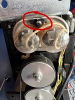
Quick update. It looks like the tape drive might indeed be the culprit of the magic smoke... Specifically the big cap next to the drive belt. See the attached photo. The cap-like burning smell and the blackened region in the photo below are all I'm going on right now. Beyond this I see nothing else that would cause me to be suspect of it...

Any thoughts?

Thanks.

TAPE_CAP.jpg
 
Quick update. It looks like the tape drive might indeed be the culprit of the magic smoke... Specifically the big cap next to the drive belt. See the attached photo. The cap-like burning smell and the blackened region in the photo below are all I'm going on right now. Beyond this I see nothing else that would cause me to be suspect of it...

Any thoughts?

Thanks.

View attachment 1278210
@Hugo HoldenWhen I toggled between the "normal" and "register" display modes I could see the signal jump from a partial screen to a full screen signal. That matches what I would expect... One

I can't understand what this means.

You will have to be much more specific with the descriptions of what you are observing for me to be able to help you, for example;

when you "saw the signal jump from a partial screen to a full screen" what were you actually looking at ? was it the face of the CRT, did you see some data on it, or the face of the oscilloscope and you saw signals, and what exactly did you see ?

I still don't know if you have seen anything at all on the CRT's face and if there is no video information, no scanning raster present, or both absent. Need more detail.

If you observe something, either on the scope trace, or the CRT's screen face, can you post a photo of it, and say what the operating conditions are at the time. Or my crystal Ball is too hazy to make any sense of it.

Also, the schematics need posting.

That oil filled capacitor may have vented, if it had the area would be wet with oil, not dry, possibly ,or the smoke was from elsewhere more likely. Normally those sorts of caps are super reliable. If we had the schematic we could probably see what it is for, it may be the motor's phase shift capacitor.
 
My guess of "partial to full screen" is that the oscilloscope trace of the raw video signal shows scanlines with "stuff" for most of the screen during register display, while it shows mostly empty scanlines during normal display. If I guessed correctly, then maybe I'll have saved patm some typing :)

The closest thing to 5100 schematics can be found in the 5100 Maintenance Information Manual (PDF pages 267-312) but those are mainly more abstract functional diagrams. I think most of the information about the display is missing there. Fortunately the built-in monitor is a commodity part --- you should be able to find schematics for that, but I can't say where. I also seem to recall @voidstar78 finding at least two different makes of VDU in his machines.

I think the tape unit capacitor is indeed for phase shift; see pages 310 or 311 in the MIM. It's a hunch that the capacitor drawn there is the same as the one that (may have) smoked here. The white wires match, though.

I have to assume there's a chance that the oil in these caps contains PCBs. If the cap doesn't say "No PCBs" on it, then that probably increases the likelihood.
 
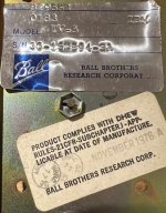
@stepleton is spot on about the video signal! (y):) My CRT matches the one @voidstar78 mentions that was made by Ball Brothers.

CRT_Model.jpg

I still have not found any other likely "hot" spots beyond that cap -- the keyboard PCB is really the only thing I haven't looked at. I've opened up all the power sections that were covered and towards the front of the machine (under the CRT, behind the power switch). Nothing really stands out. Oh, PCBs -- wow, there is something I had completely forgotten about! Will most definitely check out the cap to see if it says anything (I don't think it does). Thanks again @stepleton. I will most certainly use care working around it! On the good news front the computer also had an external tape drive with it -- I might just have a spare if that is indeed what let loose with the magic smoke.
 
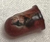
Well, I found it! 100% certain... I guess sometimes the nose is better than the eyes for chasing these things down... ;)

Here's what remains of one unhappy LED that was tucked into the front panel.

LED_MAGIC.jpg
It is the process check light -- the IBM docs show it receives +5V and comes off the display card (PDF page 295). It is a bit hard to chase from there as I seem to find the negative side labeled in two different ways... The same diagram above shows it going to -Machine Check LED (B09). On the Display Board diagrams I find what appears to be (still can't read these things well) two series resistors, one 750 ohm and one 240 ohm (PDF page 285). I have not quite figured out the rest of the circuit there but I wonder if there is a short lurking somewhere in the mix?
 
Last edited:
Well, I found it! 100% certain... I guess sometimes the nose is better than the eyes for chasing these things down... ;)

Here's what remains of one unhappy LED that was tucked into the front panel.

View attachment 1278251
It is the process check light -- the IBM docs show it receives +5V and comes off the display card (PDF page 295). It is a bit hard to chase from there as I seem to find the negative side labeled in two different ways... The same diagram above shows it going to -Machine Check LED (B09). On the Display Board diagrams I find what appears to be (still can't read these things well) two series resistors, one 750 ohm and one 240 ohm (PDF page 285). I have not quite figured out the rest of the circuit there but I wonder if there is a short lurking somewhere in the mix?
Correction: the diagram with the series resistors to the LED is on the ROS card.
 
Back
Top