• Please review our updated Terms and Rules here

IBM 5100 Keyboard Issue

Chruus

New Member
Joined
Feb 7, 2023
Messages
9
Hi all,

A friend and I have had the privilege of being able to work on an IBM 5100. We've been working on it for the past year or so, but have hit a roadblock and need some advice.

Background:
I am not a technician. I like building modern PCs and have some experience in repairing electronics (eg. 3DS). That said, I was born post 2000, so much of this old tech is over my head.
This 5100 has had a troubled life, including living in a shed for at least 10 years. The foam had returned into its primordial ooze, there were bug carcasses everywhere, and it generally just looked abused. We don't need much tech knowledge to disassemble and clean, so the bugs are gone, and the foam is replaced. As for the functionality of it, we did have to follow some basic troubleshooting to get it past the boot-up checks. We have gotten it to a point where the PC boots into the command line.

Issue & Troubleshooting:
The keyboard doesn't work. Or at least 99% of the time. Once in the command line, the cursor will be blinking and allow us to type, but pressing keys on the keyboard doesn't work. There have been three times in the past year of working on this where one of us will be pressing keys, and it will start to register inputs on the screen. It usually only registers a couple keys ("asy") or one repeatedly ("mmmmmmmmmmmmm") before it goes back to being unresponsive. We have opened up the keyboard, where it looks like the most crap got into. We cleaned it out, replaced the foam, and refitted each of the switches. After combing over the PCB several times, one of the traces appeared to have been corroded or eaten away or something. I soldered a wire to replace it, but that didn't appear to change anything. We have checked continuity on the old ribbon cable, so the issue lies within the keyboard itself.

Speculation:
1) I don't understand super well how the keyboard works, but the big copper(?) pads that the switches touch appear to have some sort of damage. They were at one point shiny, but now have large patches of dull sections. I don't know if these reduce conductivity, but if so, then that could explain why it works sporadically.
2) One or more of the ICs on the board may be faulty. I don't have any good way of testing them, I can't find their circuit diagrams online if I did, and I don't think I could find replacements either way. I really hope this isn't the issue, because it would require replacing the whole keyboard.
3) There could be a faulty capacitor or resistor. I am not certain if caps were around this long ago, but I didn't see anything that looked like a blown out cap that you'd see on an old xbox or something similar. I did measure all the resistors, and they appeared to all be within spec, but my testing left me far from certain of my results.

I have seen someone replace the keyboard on a 5110 using a modern wireless keyboard, an arduino, and some coding magic. We did try this, but couldn't get it to work. If at all possible, I would like to keep the original keyboard functional inside this PC. I understand that is a big ask for a PC as abused as this one, but replacing the keyboard is a last resort for me.

I've attached some (hopefully) relevant images below.

Here's an image of the outside of the 5100 in all its faded, battered glory.
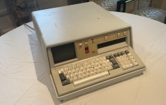
IMG_2129.jpg

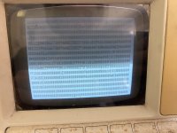
These are the registers when it boots into the console (pressing the "display registers" button). I thought I should include them in case some wizard can read theseIMG-2127.jpg
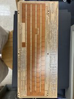
Here is the front and back of the keyboard's PCB. These are some older pictures taken before I fixed the corroded trace.
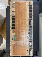
IMG-1792.jpgIMG-1793.jpg

And here are the copper(?) pads with possible corrosion or damage or whatever on them.
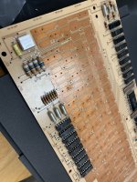
IMG-1789.jpg
 
Those axial Tant capacitors on the board are super reliable, the sort used in mil spec applications, likely ok, but you could check for shorts.

I have never seen the internals of this keyboard before, but the first thing I would want to look at is the surface of the plungers connected to the keys, can you post a photo of those ? this is the most important part to examine. There may well be nothing at all wrong with what you have shown in the photos posted.

The copper on the board may in fact have a lacquer coating on it, if it is a capacitive style keyboard. If there is no coating on the copper, and the surface of the copper is exposed, it could be a conductive keyboard, then the discs on the key plungers would be expected to be something like conductive rubber, or metal, looks less likely in this case for this design.

The photo image though looks like the copper has lacquer over it, in addition I cannot see any wear marks where contacts have been engaging it, so in that case it is very likely a capacitive keyboard. And if that is the case, likely the issue is with the discs on the plungers.

The oxidized surface looks like areas where the surface insulating lacquer has broken down, that won't cause a problem. Between the larger pads, where the keys presumably interact, it looks as though there are two thin barrier earth tracks to lower the stray signal transmission between the copper pads when the key is not depressed, more evidence that it is likely a Row- Column capacitive style keyboard.

Can you post the schematic for this keyboard. The circuit also appears to contain two of IBM's interesting custom aluminium cased modules and possibly some inductors.

The first thing in fixing something is to figure out how the design works, then start making tests with the scope.

For some reason IBM used their own numbering system on the IC's, but they will still be standard TTL's and it is possible to work out what they are in many cases.
 
Last edited:
Thanks for the response! I'll choose to rule out the caps for now. The switches are touching the PCB when resting, and not touching when depressed. I am not clear on the difference between capacitive and conductive keyboards are, but I hope the rest of this info clears that up for you.

Here's my speculation: Electricity flows through the copper pads and can make it to the other side when all keys are touching the pads. The layout of the copper pads looks to be arranged in a row / col setup (just like you said), so it figures out which key is pressed by taking the row and col that isn't conducting electricity. Again, that's a guess and I really don't know how this works, it's just a theory I came up with while trying to figure out what's wrong with it.

Also, that's great news on the ICs! I thought they were just old chips that have been out of production for decades.

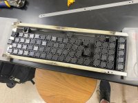
I do know that this keyboard uses IBM's beam spring switches, if that gives you a head start. I used a multimeter to check if the pads are conductive, it said they aren't. Here's a picture of the switches mounted to the faceplate:
IMG_1791-modified.JPG

I'll link a PDF of the hardware manual. Here: https://bitsavers.org/pdf/ibm/5100/SY31-0405-3_IBM_5100_Maintenance_Information_Manual_Oct1979.pdf

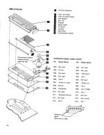
Page 26 of the PDF has an exploded view of the keyboard.
Screenshot 2023-10-11 225231.png

Page 207-210 has what appears to explain how the keyboard functions.

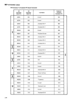
Page 296 has the pin out for the keyboard's cable.
Screenshot 2023-10-11 225414.png

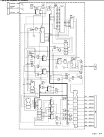
Page 299 looks similar to a circuit diagram, although I've never seen one that looks like this.
Screenshot 2023-10-11 225521.png

Hope these help!
 
Be very careful with the beam spring key switches. When one of those plates falls off, they are a pain to get back on. The ICs are IBM part numbers but you can check them against this cross reference list: http://bitsavers.trailing-edge.com/pdf/ibm/logic/IBM_Part_Number_to_Industry_Part_Number.txt

How did you fix the "corrosion"? They are capacitive so they won't register continuity via an ohmmeter. Other than a surface wipe, the keyboard PCB looks fine. You might very carefully wipe the key switch plates but they don't look that bad either.
 
Just linking to the earlier thread about the 51[012]0 keyboard and the Arduino replacement, which goes into some detail about the theory of operation of these things:
https://forum.vcfed.org/index.php?t...ard-replacement-pin-out-measurements.1238748/

I'm sorry I don't have much more time to help out right now, but I hope that thread can offer some inspiration on what to probe!
Thanks!

Be very careful with the beam spring key switches. When one of those plates falls off, they are a pain to get back on.
Unfortunately, about half of the plates were disconnected when I started working on it. I did need to take them off to clean them though, so I got pretty good at putting them back on. That said, the insides of these switches were noticeably rusted. I'll look up how capacitive switches work later tonight, but does this rust (or any other gunk under the plate & in the switch) hurt the capability of the switch? Besides mechanically making it inconsistent to press.

The ICs are IBM part numbers but you can check them against this cross reference list: http://bitsavers.trailing-edge.com/pdf/ibm/logic/IBM_Part_Number_to_Industry_Part_Number.txt
Awesome, thank you so much!

How did you fix the "corrosion"?
I haven't. I couldn't figure out what was wrong and guessed that it was corrosion was the issue, but it sounds like that's it.

They are capacitive so they won't register continuity via an ohmmeter.
Good to know. Is there a way for me to test them to make sure it works, or is it safe to assume that they're fine?
 
This is a very very special keyboard you have here, everything that can be done should be done to try to preserve it.

From the manual it appears that this is a reverse action capacitive keyboard:

When a key is pressed, a flyplate in the key module moves away from the printed circuit pads on the keyboard PC board and decreases the capacitance at that key position. A pressed key is sensed when a sample pulse is not transmitted.

This is interesting, because to work, all of the flyplates and the coated copper pcb layer they are pressing on, would have to be in perfect order. One defective one could possibly (depending on the rest of the design) disable the entire keyboard with a stuck key effect.

Though I don't think that area where the pcb has changed color and the coating looks mildly defective is likely the cause of your trouble, if you gently touch the meter probes in areas where the surface looks altered (don't scratch it) on the pcb, check for conductivity. It would be easy to re-lacquer the pcb, but it would be critical it was the right product with a very thin layer.

I'm not sure if these plates have a dielectric film over their conductive layer. There is obviously an insulating film over the pcb surface.

Capacitive pads do not conduct any DC. They create a low capacitance signal coupler, of high frequency AC The capacitance is usually less than 20pF or so, it depends on the geometry of the plates and the thickness of the insulating layer (dielectric) and the dielectric constant..

The small capcitance allows the transmission of a very high frequency signal, usually just the rising and falling edges of an applied square wave. ( If you are aware of the Fourier theorem, you would know that a square looking voltage waveform, say that comes out of a logic IC, has a fundamental frequency and many higher order harmonics, at least up to the 23rd harmonic to make it look reasonably square). In short, the rising and falling edges of the wave, represent the high frequency component, get coupled by the low value capacitor, into an amplifier circuit that detects that.

I would very carefully inspect those rectangular fly plates and find out if they are coated with any dielectric, a gentle touch with the meter probes. Be gentle with them.( How are they attached, do they have a foam backing ?) If they have a surface dielectric layer it would be critical that any replacement plates had a dielectric layer that was no thicker. Like I say, they may have just relied on the pcb lacquer to be the dielectric (insulating layer) and the surface of the flyplate conductive, but that might have been more risky for long term wear, given that there are earthing barrier strips between the pcb pads..

To get to grips with how capacitive keyboards work, read this article I wrote about the one in the SOL-20. In this case though, the capacitance increases with a key press. In your keyboard it decreases, because the plates move away from the pcb pads with a key press, but otherwise the operating principles are basically the same.

www.worldphaco.com/uploads/HARDWARE_DIAGNOSTIC_TOOL_FOR_THE_SOL.pdf

Given the absence of discrete transistor amplifiers to process the rising and falling edges of the key signals on your keyboard, possibly some of the IC's on it could be cmos types, However, it could be, that those aluminium body IBM modules are some type of analog amplifier.
 
Last edited:
Wow, thanks for sharing your experience! I hope I can preserve this keyboard, and by extension the PC, to the best of my abilities.

I apologize, I'm really struggling to grasp how the key switch actually functions. The last thing I want to do is disregard your research and expertise, but please keep in mind that I'm not even out of high school, much less an electrical engineer. That said, I will do my best to learn fast and work with y'all.

I would very carefully inspect those rectangular fly plates and find out if they are coated with any dielectric, a gentle touch with the meter probes. Be gentle with them.( How are they attached, do they have a foam backing ?) If they have a surface dielectric layer it would be critical that any replacement plates had a dielectric layer that was no thicker. Like I say, they may have just relied on the pcb lacquer to be the dielectric (insulating layer) and the surface of the flyplate conductive, but that might have been more risky for long term wear, given that there are earthing barrier strips between the pcb pads..
Here is my understanding of the key/switch's function: Essentially, the plate has two legs that connect to a springy metal bar in the switch housing. This bar is connected to a standard coiled spring that pushes the switch stem up and pulls the fly plate up. When compressed, the plate applies more pressure to the PCB until it buckles back into the housing, not touching the PCB anymore.

The switches lock into the front plate. It's a friction fit, but there's a notch to help it grab better. There was foam between the top of the switch and bottom of the faceplate, which was disintegrated when I found it. Before replacing it, the keys sat in the faceplate very loosely and could be moved up/down a millimeter or two. I've replaced it with some new foam, but the thickness may not be to spec.

How should I go about testing the fly plates/dielectric layer?


Thanks again for your replies
 
Beam spring info: https://deskthority.net/wiki/Beam_spring

As for testing, the only way I know how is to have the keyboard installed and pressing keys. If you have no response or intermittent response, you should check the logic on the keyboard and check the cable on both ends. It is a bit tricky to remove the keyboard connector from the planar but I would check continuity on the each of the pins on the cable while you're at it.

It is unlikely that the key switches would fail 99% of the time and work occasionally. That looks more like the sense circuitry or the data being passed (or not) to the planar.
 
Wow, thanks for sharing your experience! I hope I can preserve this keyboard, and by extension the PC, to the best of my abilities.


How should I go about testing the fly plates/dielectric layer?


Thanks again for your replies
According to the wiki link:

"The switch uses a capacitive contact mechanism on what IBM called a "pad card" – a two layer PCB covered with an insulating substrate. On the lower layer of the pad card, there is a contact for each key on the keyboard, all of which are attached to an oscillator. On the upper layer of the pad card, there are two contacts for each key, one of which sits above the lower layer's contact, and the second is beside it, and is attached to a sensor. At the bottom of the beam spring key module is a so-called 'fly plate' – a piece of conductive plastic which sits on top of the pad card over the two contacts on the upper layer. The oscillator drives a signal on this arrangement of conductive pads, and three capacitors are formed – one between the contact on the back of the Pad Card, and the one directly above it, one between the latter contact and the fly plate, and one between the fly plate and the other contact on the top layer, which in turn is connected to a sensor. The capacitance between the lower contact and the one above it remains constant, and is used as a baseline by the sensor".

Though the look of your keyboard suggests the flyplate increases the capacitance across two of the adjacent pads on the pcb, and each of those has a constant capacitance to the ground plane on the other side of the pcb.

So it would appear the flyplate is made of conductive plastic. Of course whether or not the the surface of it is electrically conductive is another matter. it would not matter much because the pcb has an insulating layer, I do not know, I have never seen or tested one. As I said a light touch with the meter probes would show if they are conductive cross their surface, or not. The capacitive pads in other keyboards are generally a thin aluminium layer with a plastic film on both sides, (as in the SOL-20 keyboard) though people have replaced those with films that are conductive on one surface and plastic on the other. Hopefully all the flyplates are ok.

One thing though, the design of the keyboard expects that all of the flyplates are in position and applied to the pcb surface. A key detect only occurs when one flyplate lifts from the surface. Though it must have been configured so that if one was lifted (key pressed) that the circuit could still respond to other keys, but I'm not certain if it could, if they shared the same Row or Column. For testing then, it is best to have all the keys/flyplates installed.
 
Also, looking at the schematic, there are a number of things that can be checked with the scope. The board has its own 25kHz clock oscillator. There are flip flops that generate 1.5mS pulses with keys that open & close. The are unique signals for CMD and Shift. There is a sense amplifier for the key matrix. An output latch for the Data. That schematic, if it is the only one, needs to be correlated with the actual parts on the board. Probably most of it will be working.

It is almost certain that the large 24 pin IC on the board is a 74154, a 4 line to 16 line decoder used to scan the keyboard matrix, it can be scoped too, its input pin numbers match up:


Basically it will be applying square waves to the matrix, the output signals from the matrix will be the differentiated rising & falling edges, these are amplified by the sense amplifier. If you look on the rear of the pcb, you will see there are 4 long tracks running the length of the pcb between the large earth bus areas, likely these are the ones that will end up at the input of the sense amplifier. It is a matter of figuring out how what you have in front of you correlates with that schematic. Likely one of the rectangular aluminium modules is the sense amplifier and the other the 25kHz oscillator.

So there are a good number of things already that could be tested.
 
Last edited:
I apologize for the delay, school & college apps have kept me super busy. That said, I should have some more free time to work on the 5100 with fall/winter breaks coming up.

Also, looking at the schematic, there are a number of things that can be checked with the scope.
Just to clarify, are you talking about an oscilloscope? The only one I have access to is my teacher's old analogue scope - it's tan with a CRT (or whatever the green, monochrome screen is). I'm not very comfortable with how it works, but I can figure it out.

Also, should I test the keyboard with nothing attached to the PCB? I assumed that it wouldn't function without the keys being held to the PCB, but I guess for testing it would be fine. I also don't know if I should be worried about ESD while it's plugged in.

Thanks for all the replies! I'll get to testing as soon as I know I won't blow something up.
 
I apologize for the delay, school & college apps have kept me super busy. That said, I should have some more free time to work on the 5100 with fall/winter breaks coming up.


Just to clarify, are you talking about an oscilloscope? The only one I have access to is my teacher's old analogue scope - it's tan with a CRT (or whatever the green, monochrome screen is). I'm not very comfortable with how it works, but I can figure it out.

Also, should I test the keyboard with nothing attached to the PCB? I assumed that it wouldn't function without the keys being held to the PCB, but I guess for testing it would be fine. I also don't know if I should be worried about ESD while it's plugged in.

Thanks for all the replies! I'll get to testing as soon as I know I won't blow something up.
Wow, still at school, you are on a fairly steep learning curve with this sort of problem. However you do seem very capable and confident (but not overly so) and obviously you are a very quick study.

You probably will be able to repair this keyboard, but likely it will require the oscilloscope.

If you can borrow your teacher's scope, and get familiar with the controls, looking at various signals, square waves, sine waves of various frequencies and amplitudes. Become familiar with it and how it enables you to see voltages that are changing with time. Your teacher will give you some tips. General it should be set on DC coupling and you would use a x10 probe scoping around these sorts of circuits (has a 10meg input resistance). You can use a x1 probe (has a 1Meg input resistance) for TTL circuits too, but it is still better not to apply any significant loads to the circuits you are testing. A typical digital multi-meter has a 10 Meg input resistance too.

In the meantime, to help you understand how the capacitive switches work, look up how a circuit with a low value series capacitor and a resistor to ground makes a "differentiator" and passes the components of the signal that have the highest rates of change with time (highest frequencies) and makes a "high pass" filter. This is the principle of operation of these switches. And how a circuit with a series resistor and a capacitor to ground creates an integrator, or a low pass filter.

It would also help to look up the basic types of TTL logic chips used in a keyboard like this, typically gates like NAND, AND, OR, NOR, XOR, Inverter gates, Flip flops JK types, D types, and other common 74 series logic counter IC's. Also look up the 74154 that I gave the link for.

Generally, if you are scoping TTL logic, you see voltages on the output pins change abruptly from close to 0 volts to around 4V, ( not 5v unless there are pull up resistors to the +5V rail). This is because of the design of the output stage inside the TTL chips. The logic threshold level at their inputs, where a state changes occurs is around the 1.2V figure.

On the other hand with CMOS logic IC's, powered from 5V, you would find the output voltage swings very close to between zero to +5V, because of the output stages in these chips, and their logic threshold levels are about 2.5V or half the supply voltage.

One way to spot dud IC's is when the output voltage is either stuck high or low, when it should not be according to the chips logic table, or when it is at some indeterminate logic level inbetween.

If you want to get into repairs of vintage computers, apart from the scope, it is worthwhile buying TI's TTL data book, because there is a lot of additional information in it about the IC's and their operations:

 
Great era-specific reference! Note that it's online at: https://archive.org/details/bitsavers_tidataBookForDesignEngineers2ed_29954976

You can download a 28.6 MB PDF for local use.
 
Great era-specific reference! Note that it's online at: https://archive.org/details/bitsavers_tidataBookForDesignEngineers2ed_29954976

You can download a 28.6 MB PDF for local use.
Except that a download that you view on a VDU is nowhere near as good (not even close) as having the real book on your desk, or in your lap, while you are working. Or maybe leave it in the bathroom and you can read it on the toilet where I have absorbed probably 20% of my current knowledge.
 
Winter break is here, which means I am finally free to work on the 5100!

I hooked up the scope to that main 24-pin IC, and it appears to be functional after following the datasheet Hugo Holden sent.

I have two questions. One, am I testing it right? I attached a video of how I'm using the scope. I'd like to make sure I'm doing it right before I go test all 25+ of the other ICs. The other is where would I find datasheets for these other ICs? I've looked around and find 10 ICs with the same numbers, all of them releasing post 1980. Is there a website/database that I'm missing?

Here's the video. I forgot to mention in the video: A is high. B, C, D, and G2 are low.

Thanks for helping me get this far.
 
Last edited:
Look for and change on the strobe signal when you press a key and see if after you do the keyboard data bits change.

I had thought somewhere somebody had compiled a list of the IBM IC numbers vs 74 numbers, but I don't know where that is.

Sometimes IC's like the 7490, '92 and '93 '96 can be identified because of their non standard power pins.

On the board, I think there are two 1.5mS monostable IC's that should fire with key presses and releases, these can be identified by a capacitor and timing resistor connected to their pins. Look up monostable IC's in the 74 family like the 74123 and 74221. Those pulse could be checked.

Probably checking random pulses with the scope won't help until we know what all the IC's are and a better schematic can then be drafted. At least if there are pulses on the 75154, likely the master 25kHz clock is running fine.

Of course, it is possible that the keyboard is in fact electrically working, but not working due to problematic fly plates. To test it properly, it really needs to be reassembled because the system relies on all of the plates being opposed to the pcb, and a key detected when one lifts off the surface. Electrical testing then can be done from the other side of the pcb.
 
Last edited:
I cannot reach the backside of the PCB while assembled due to a plastic cover being required to screw everything together. That said, I can still reach all the ICs at the top of the board.

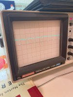
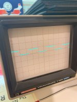
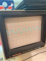
Here's my findings on the 74154 (with the keyboard assembled). The settings, aside from C, are 5V per bar on the Y and 0.1ms per bar on the X.

0-3: Looks like it's given a constant stream of 1's
IMG_2255.JPG

4-15: Stuck on high

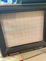
G1: oscillates from High to Low every 0.2ms.
IMG_2256.JPG

G2, D: Stuck on low

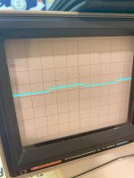
C: This may be the issue. Oscillates from high to Low every 0.8ms. But high is barely anything (I'm not sure what the exact value is, but it's less than 1V). The image is on a smaller scale to more clearly show the oscillation.
IMG_2259.JPG

B: Oscillates from High to Low every 0.8ms
IMG_2257.JPG

A: Oscillates from High to Low every 0.4ms
IMG_2258.JPG

I'll try to see where the trace to C goes. Since it's an input, the issue probably lies on the other end (if I'm not an idiot).
 
Last edited:
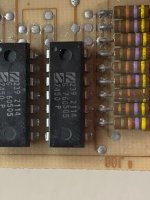
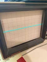
Jackpot! The IC labeled 760505 is the one with the weird low signal. C connects to the top-right pin (when the hole is on top). Checking all the others, they all have 5V, constant or oscillating. I think this is the culprit, but we'd need a circuit diagram to make sure.

Here's the IC in question:
IMG_2264.JPG

Here's what the top right pin was reading (same as C):

IMG_2261.JPG

I'll wait to hear from the pros before I do anything else. Thanks, as always.
 
Back
Top